
Manual

Connections and controls
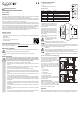
1 Opening for wall mounting
2 LED
3 RFID/ngerprint sensor with LED ring
Connecting cable:
Colour Inscription Function
Red 9 - 24 V/DC Operating voltage 9 - 24 V/DC
Black GND GND/ground
Yellow OPEN Door opener button
Green NC NC (normally closed) contact of relay
Brown COM COM (centre contact) contact of relay
White NO NO (normally open) contact of relay
Installation and connection
Use suitable screws and, if necessary, dowels
to mount the mounting plate with the module
on the wall (see gure on the right) depending
on the type of wall.
The included mounting frame can be pre-in-
stalled depending on the substrate and instal-
lation position, and the access system should
then be screwed tight. Suitable screws and, if
necessary, dowels should be used depending
on the substrate.
A hole for the connecting cable must be drilled
before fastening.
Ensure that no cables or wires
are damaged when drilling holes
or tightening screws.
Wiring should be carried out according to the following examples.
Ensure that there is suitable insulation (e.g. heat shrink tubing).
A protective diode is included for connecting a door opener. It protects the electronics from damage caused
by voltage surges. Ensure the correct polarity, as shown in the following connection examples (when con-
nected, the ring on the protective diode must face the positive pole/+).
Attention!
Never switch the mains voltage via the potential-free changeover contact! There is a risk of fatal
electric shock! Observe the permissible contact rating; see “Technical data” chapter.
Use suitable cables with different colours. Note the colours and store this information together
with these instructions. When connecting the cables, pay attention to the correct polarity (plus/+
and minus/-).
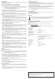
Connection to conventional voltage/power supply:
When a conventional power supply unit should be
used, observe the wiring diagram on the right.
A) “Fail Secure” door opener: Releases the lock-
ing latch only when its operating voltage is applied
(common design for front doors).
B) “Fail-safe” door opener: releases the locking
latch only when the operating voltage is missing
(uncommon design, e.g. used for escape route
doors, which can be opened in the event of a power
outage).
1 Access system
2 Door opener button
3 Power adapter
4 “Fail-Secure” door openers
5 “Fail-Safe” door openers
The included diode must be connected correctly
near the door opener to protect the access system
from voltage surges.
Connecting to alarm system
Observe the operating instructions for the alarm
system used. The access system relay switches
when a valid transponder is recognised or when
a stored nger is placed on the sensor. The alarm
system can thus be enabled or disabled.
Operation
Switch on the operating voltage after installation and connection. The access system LED lights up red. This
indicates that the access system is in standby mode. You can now start programming, see next chapter.
Operating instructions
RFID/ngerprint access system
Item no. 2380476
Intended use
This product is designed to prevent unauthorised access to doors (e.g. in an ofce) and to activate/disable
alarm systems. Control can be exercised via suitable transponders or ngerprints.
Holding a paired user transponder in front of the reading surface or placing a stored nger on the ngerprint
sensor activates a potential-free relay changeover contact (see contact rating under “Technical data”). This
can be used, for example, to control a door opener or an alarm system.
The product is intended for vertical installation on a wall and is suitable for indoor and outdoor use (IP 66).
For safety and approval purposes, do not rebuild and/or modify this product. Using the product for purposes
other than those described above may damage the product. In addition, improper use can cause hazards
such as a short circuit, re or electric shock. Read the operating instructions carefully and store them in a
safe place. Only make this product available to third parties together with its operating instructions.
This product complies with statutory, national and European regulations. All company and product names
contained herein are trademarks of their respective owners. All rights reserved.
Delivery content
• RFID/ngerprint module
• Fasteners (2x special screws with matching L-key, 4x screw head stickers, mounting frame with 2x screws
and 2x dowels)
• Master transponder
• 1N4004 diode (for relay changeover contact)
• Operating instructions
Up-to-date operating instructions
Download the latest operating instructions at www.conrad.com/downloads or scan the QR code shown.
Follow the instructions on the website.
Description of symbols
The symbol with an exclamation mark in a triangle is used to highlight important information in
these operating instructions. Always read this information carefully.
The arrow symbol indicates special information and tips on how to use the product.
Safety information
Read the operating instructions carefully and observe in particular the safety instruc-
tions. If you do not follow the safety information and information on proper handling in
these operating instructions, we will assume no liability for any resulting personal injury
or damage to property. Such cases will invalidate the warranty/guarantee.
• This product is not a toy. Keep it out of the reach of children and pets.
• Protect the product from extreme temperatures, impacts, ammable gases, vapours and
solvents.
• Handle the product carefully. Jolts, impacts or a fall even from a low height may damage the
product. Do not place the product under any mechanical stress.
• Do not mount or connect the product when it is connected to a power supply.
• Never exceed the contact rating for the potential-free changeover contact specied in chapter
“Technical data”. Never switch the mains voltage, as this can cause life-threatening electric
shock!
• Always observe the safety and operating instructions of any other devices which are con-
nected to the product (e.g. door openers and alarm systems).
• If it is no longer possible to operate the product safely, stop using it and prevent unauthorised
use. Safe operation of the appliance can no longer be guaranteed if it shows visible signs of
damage, malfunctions, has been exposed to unfavourable storage conditions or signicant
transport loads.
• For installations in industrial facilities, follow the accident prevention regulations for electri-
cal systems and equipment issued by the national safety organisation or the corresponding
national authority.
• Do not leave packaging material lying around carelessly. It may become a dangerous toy
for children!
• Maintenance, modications and repairs must be carried out by a technician or a specialist
repair centre.
• If you are not sure how to operate the product correctly, or if you have any questions that are
not answered in these operating instructions, contact us or another specialist.
1
2
3
4
5
1
2
3