English...................1 Francais...............25 Italiano.................49 SHINDAIWA OWNER’S/OPERTOR'S MANUAL T350 GRASS TRIMMER C350/B450 BRUSHCUTTER T350 C350/B450 WARNING! Read this manual and familiarize yourself with its contents. This machine is designed for cutting grass, weed, and bushes. Do not use this machine for other purposes. Minimize the risk of injury to yourself and others. Do not operate or service this machine unless you clearly understand this manual.
Introduction Attention Statements Shindaiwa 350 and 450-series hand held power equipment has been designed and built to deliver superior performance and reliability without compromise to quality, comfort, safety or durability. Shindaiwa’s high-performance engines represent the leading edge of 2-cycle engine technology, delivering exceptionally high power with remarkably low displacement and weight.
General Safety Instructions Work Safely Stay Alert Trimmers and brushcutters operate at very high speeds and can do serious damage or injury if they are misused or abused. Never allow a person without training or instruction to operate this unit! You must be physically and mentally fit to operate this unit safely. WARNING! Never make unauthorized attachment installations.
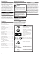
The Properly Equipped Operator Wear hearing protection devices and a broad-brimmed hat or helmet. Always wear eye protection such as goggles or safety glasses to shield against thrown objects. Wear close-fitting clothing to protect legs and arms. Gloves offer added protection and are strongly recommended. Do not wear clothing or jewelry that could get caught in machinery or underbrush. Secure long hair so that it is above shoulder level.
Safety Labels IMPORTANT! T350 Safety and Operation Information Labels: Make sure all information labels are undamaged and readable. Immediately replace damaged or missing information labels. New labels are available from your local authorized Shindaiwa dealer. C350/B450 Checking Unit Condition WARNING! A cutting attachment shield or other protective device is no guarantee of protection against ricochet.
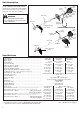
Unit Description T350 TRIMMER Using the accompanying illustrations as a guide, familiarize yourself with this unit and its various components. Understanding the product helps ensure top performance, long service life, and safer operation. Ignition Switch Do not make unauthorized modifications or alterations to any of these units or their components.
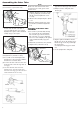
Assembly Procedure Prior to Assembly Before assembling, make sure you have all the components required for a complete unit: T350 ENGINE ASSEMBLY Engine assembly Outer tube assembly Cutting attachment shield Cutting attachment Handlebar Kit containing cutting attachment shield mounting bracket and hardware, operator’s handle mounting bracket and hardware, gearcase tool holder, this manual and tool kit for routine maintenance.
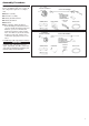
Assembling the Outer Tube NOTE: T350 (1) Loosen the 2 joint bolts fully. JOINT BOLT JOINT Make sure that the throttle cable is built into the cable guide of the throttle lever. (4) Loosen the stopper bolt of the throttle grip. Remove the stopper bolt and nut. (5) Fully loosen the clamp bolt of the throttle grip. (8) Shift the throttle lever back to original position, pulling the ground wire and throttle cable and tighten the screw securely. (9) Remove the bolt tightening the cylinder cover.
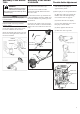
Assembly of the Handle T350 WARNING! NEVER operate this machine without the front handle. Operating without the front handle may result in serious injury. NOTE: Tighten four bolts diagonally to properly secure the handle. NOTE: Adjust the handle at the best position for operator comfort. (1) Put four square nuts in the recesses on the underside of the barrier. Assembly of the Handle C350/B450 (1) Loosen the two bolts of the lower cap and remove the lower cap.
Cutting Attachment Shield Assembly WARNING! NEVER operate this machine without the cutting attachment shield. Operating without the cutting attachment shield may result in serious injury. (A) Cutting Attachment Shield (1) Insert the cutting attachment shield between the outer tube and the lower clamp. Loosen the nut and bolt which are tightening the lower clamp if the cutting attachment shield does not fit with the lower clamp.
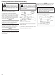
Installing a Blade (1) Make sure the switch is off and the engine is stopped. (2) Wear gloves to protect your hands. (3) Turn the unit over so the saw holder flange extending from the gear case is facing up. (4) Using the small end of the plug wrench, loosen the bolt (turn clockwise) and remove the bolt, bolt guard, and holder B. (5) Slide the safety clip as shown in the illustration.
Filling The Fuel Tank Mixing Fuel WARNING! CAUTION! Minimize the risk of fire, burns, and personal injury! This engine is designed to operate on a 50:1 mixture consisting of unleaded gasoline and a premium 2-cycle mixing oil only. Use of Non-approved mixing oils can lead to excessive maintenance costs and/or engine damage. STOP engine before refueling.
Starting the Engine WARNING! MAKE SURE THE BLADE IS WELL CLEAR OF ANY INTERFERENCE. Before starting the engine, place unit on clear, level surface. Make sure you have good secure footing and always keep a firm grip on the machine. THE CUTTING ATTACHMENT MAY ROTATE WHEN THE ENGINE STARTS.
Stopping the Engine Idle the engine briefly before stopping, then slide the ON-OFF switch to the “O” (for STOP) position. (3) If a tachometer is available, the engine idle speed should be adjusted to 2,750 min-1 (rpm) NOTE: WARNING! The cutting attachment continues rotating for a while after the switch is turned off. Carburetor fuel mixture adjustments are preset at the factory on units with emission control systems and cannot be serviced in the field.
Recommended Cutting Attachments Operation Using A Blade (1) After starting the engine, pull the throttle lever gradually. The engine speed increases and the blade will start rotating. (2) When the throttle lever is released, the engine goes back to idle speed automatically. CAUTION! To prevent possible engine damage, do not allow the machine to run at high speeds without a load. Avoid operating the engine at low speeds. Doing so can lead to rapid clutch wear.
Using a Brushcutter With a Trimmer Head You may install one of several types of Shindaiwa trimmer heads on your TC350/B450 trimmer or brushcutter, each with features for specific applications and/or operational requirements. For proper operation, always refer to the instructions accompanying the trimmer head being used. Available trimmer head styles include: Engine Operating Speeds Operate at full throttle while cutting grass. CAUTION! Operation at low rpm can lead to premature clutch failure.
10 Hour Maintenance 50 Hour Maintenance Muffler Maintenance Remove the air cleaner element from the carburetor and clean it thoroughly with soap and water. Squeeze out excess, let dry and reassemble the element. Cleaning Remove and clean the cylinder cover and clean grass and dirt from the cylinder fins. (350 only) CAUTION! Do not operate the machine if the air cleaner or element is damaged, or if the element is water-soaked.
Long Term Storage Blade Sharpening Whenever the unit will not be used for 30 days or longer, use the following procedures to prepare it for storage: With the file or a grinder, file a blade as follows. Clean external parts thoroughly and apply a light coating of oil to all metal surfaces. Drain all the fuel from the fuel tank. IMPORTANT! All stored fuels should be stabilized with a fuel stabilizer such as STA-BIL™.
Troubleshooting Guide Engine Does Not Start What To Check Possible Cause Remedy Faulty recoil starter. Fluid in the crankcase. Internal damage. Consult with an authorized servicing dealer. NO Loose spark plug. Excess wear on cylinder, piston, rings. Tighten and re-test. Consult with an authorized servicing dealer. NO Fuel incorrect, stale, or contaminated; mixture incorrect.
Troubleshooting Guide (Continued) Low Power Output What To Check Is the engine overheating? Engine is rough at all speeds. May also have black smoke and/or unburned fuel at the exhaust. Engine is knocking. 20 Possible Cause Remedy Operator is overworking the unit. Cut at a slower rate. Carburetor mixture is too lean. Consult with an authorized servicing dealer. Improper fuel ratio.
Troubleshooting Guide (Continued) Additional Problems Symptom Poor acceleration. Engine stops abruptly. Engine difficult to shut off. Cutting attachment moves at engine idle. Excessive vibration Attachment will not rotate Possible Cause Remedy Clogged air filter. Clean or replace the air filter. Clogged fuel filter. Replace the fuel filter. Lean fuel/air mixture. Consult with an authorized servicing dealer. Idle speed set too low. Adjust: 2,750 min-1 Switch turned off.
Declaration of Conformity DECLARATION OF CONFORMITY We hereby declare the Shindaiwa Engine Engine Brushcutter, Model RM 350 (T350/EC1, C350/EC1). meets the following respective requirements. Council Directives: 89/336/EEC as amended 98/37/EC as amended 2000/14/EC as amended 2004/26/EC as amended Standard taken: EN 292 parts 1&2 ISO 11806 CISPR 12 Measured sound power level: 113dB(A) Guaranteed sound power level: T350/EC1:114dB(A), C350/EC1:115dB(A) Technical documentation is kept by: K. Maeda DIV.
Declaration of Conformity DECLARATION OF CONFORMITY We hereby declare the Shindaiwa Engine Engine Brushcutter, Model RM 450 (T450/EC1, B450/EC1). meets the following respective requirements. Council Directives: 89/336/EEC as amended 98/37/EC as amended 2000/14/EC as amended 2004/26/EC as amended Standard taken: EN 292 parts 1&2 ISO 11806 CISPR 12 Measured sound power level: 115dB(A) Guaranteed sound power level: 117dB(A) Technical documentation is kept by: K. Maeda DIV.
NOTES: Shindaiwa Inc. 11975 S.W. Herman Rd. Tualatin, Oregon 97062 USA Telephone: 503 692-3070 Fax: 503 692-6696 www.shindaiwa.com Shindaiwa Kogyo Co., Ltd. Head Office: 6-2-11, Ozuka-Nishi Asaminami-Ku, Hiroshima 731-3167, Japan Telephone: 81-82-849-2220 Fax: 81-82-849-2481 ©2005 Shindaiwa, Inc. Part Number 62102-94310 Revision 2/05 Shindaiwa is a registered trademark of Shindaiwa, Inc. Specifications subject to change without notice.