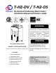
T‐H2‐DV / T‐H2‐OS On‐Demand Condensing Water Heater Installation Manual and Owner’s Guide WARNING This product must be installed and serviced by a licensed plumber, a licensed gas fitter, or a professional service technician. Improper installation and/or operation, or installation by an unqualified person, will void the warranty.
Contents CONTENTS SPECIFICATIONS T‐H2‐DV and T‐H2‐OS Installation Manual SPECIFICATIONS………………………………... 2 INTRODUCTION……………………………….… 3 SAFETY GUIDELINES…………….……………..4 INSTALLATION………………………………..…. 5 General………………………………………..… 6 Included Accessories…………………..… 6 Optional items…………………………..….. 7 Warning for Installations………..…..... 8 High‐altitude region support functions…9 T‐H2‐OS Installation…………………….… 9 T‐H2‐DV Installation………..…………..… 10 Venting Instructions…………………….... 10 Gas Supply / Gas Pipe Sizing………...
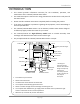
Introduction INTRODUCTION • This manual provides information necessary for the installation, operation, and maintenance of the T‐H2‐DV/T‐H2‐OS water heater. • The model description is listed on the rating plate which is attached to the side panel of the water heater. • Please read all installation instructions completely before installing this product. • If you have any problems or questions regarding this equipment, consult with Takagi or its local representative.
Safety Guidelines SAFETY GUIDELINES GENERAL 1. 2. 3. 4. 5. Follow all local codes, or in the absence of local codes, follow the most recent edition of the National Fuel Gas Code: ANSI Z223.1/NFPA 54 in the USA or CAN/CSA B149.1 Natural Gas, Propane Installation Code in Canada. Properly ground the unit in accordance with all local codes or in the absence of local codes, with the National Electrical Codes: ANSI/NFPA 70 in the USA or CSA standard C22.1 Canada Electrical Code Part 1 in Canada.
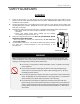
Installation INSTALLATION All gas water heaters require careful and correct installation to ensure safe and efficient operation. This manual must be followed exactly. Read the “Safety Guidelines” section at the beginning of this manual. WARNING • Installation and service must be performed by a qualified installer (for example, a licensed plumber or gas fitter), otherwise the warranty by Takagi will be void.
Installation GENERAL 1. Follow all local codes, or in the absence of local codes, follow the most recent edition of the National Fuel Gas Code: ANSI Z223.1/NFPA 54 in the USA or CAN/CSA B149.1 Natural Gas, Propane Installation Code in Canada. 2. The manifold gas pressure is preset at the factory. It is computer controlled and should not need adjustment. 3. Maintain proper space for servicing. Install the unit so that it can be connected or removed easily. Refer to p. 8, p.9 and p. 10 for proper clearances.
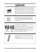
Installation OPTIONAL ITEMS 1. TM‐RE30 Temperature Remote Controller The TM‐RE30 Temperature Remote Controller has two functions. It allows the output temperature from the T‐H2‐DV/T‐H2‐OS to be adjusted within the range of 100 °F to 185 °F, and it also works as a diagnostic tool that will give a concise error code whenever there is a problem with the unit.
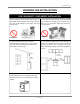
Installation WARNING FOR INSTALLATIONS FOR YOUR SAFETY, READ BEFORE INSTALLATION: Do not install the heater where water, debris or flammable vapors may get into the flue terminal. This may cause damage to the heater and void the warranty. Do not have the vent terminal pointing toward any opening into a building. Do not locate your heater in a pit or location where gas and water can accumulate.
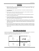
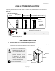
Installation HIGH‐ALTITUDE INSTALLATIONS Check the elevation where your water heater is installed. Set dipswitches shown in the table below depending on the altitude. These dipswitches (No. 5 and No. 6) are on the computer board on the left bank only. Left bank of dipswitches 2,500 to 4,000 ft 4,000 to 5,000 ft Over 5,000 ft ON OFF OFF ON N O N O Switch No.5 Switch No.
Installation T‐H2‐DV INSTALLATION T‐H2‐DV is equipped with a thermistor and hi‐limit switch for the exhaust gas, detecting excess temperatures within the flue and enabling the unit to safely stop operations if needed. These components are always monitoring exhaust gas conditions in order to prevent heat damage to PVC (Plastic) venting if PVC is used. If the exhaust gas temperature exceeds 140°F, these components will enable the unit to safely stop operations.
Installation ‐Exhaust vent (PVC & ABS vent) ‐ The T‐H2‐DV can be connected with PVC or ABS venting (temperature rated up to 149°F). However, TAKAGI recommends PVC (or ABS) venting certified to ULC S636 standards.
Installation • • • Do not common vent this appliance with any other vented appliance (Do not terminate vent into a chimney. If the vent must go through the chimney, the vent must run all the way through the chimney with Category III / IV approved or Special BH vent pipe). The maximum length of exhaust vent piping must not exceed 50 ft. (deducting 5 ft. for each elbow used in the venting system). Do not use more than 5 elbows. When the horizontal vent run exceeds 5 ft., support the vent run at 3 ft.
Installation ‐PVC Venting Illustrations‐ Wall Roof Roof Flashing Fire stop Connection between exhaust vent collar and PVC piping See below for instructions. Connection between exhaust vent collar and PVC piping See below for instructions. 1. Connect the TH‐PA01 PVC adaptor* directly on the exhaust vent collar of the T‐H2‐DV. 2. Connect a 4” PVC coupler to the TH‐PA01 PVC adaptor. 3.
Installation ‐Stainless steel Venting illustrations‐ Vertical Installation Diagram Horizontal Installation Diagram Rain Cap Wall Roof Roof Flashing Sidewall Vent Terminator Fire stop • Regarding the clearances from the exhaust terminator to the air inlet or opening, refer to the next few pages. • Follow all vent system manufacturer’s instructions and all local codes. • Do not common vent or connect any vent from other appliances to the T‐H2‐DV vent.
Installation ‐Vent clearances‐ Canada Direct vent and other than Direct Vent U.S.A Direct vent Other than Direct Vent 1 foot A Clearance above grade, veranda, porch, deck, or balcony. 1 foot 1 foot B Clearance to window or door that may be opened. 3 feet 1 foot 4 feet from below or side opening. 1 foot from above opening.
Installation ‐Additional clearances ‐ Please follow all local and national codes in regards to proper termination clearances. In the absence of such codes, the following clearances can be used as guidelines. Local codes supersede these guidelines. For sidewall terminations 2ft. 3ft. 1ft. 1ft. 2ft. 1ft. 3ft. 1ft. 3ft. Inside corner Exhaust termination For multiple sidewall exhaust terminations (e.g. multi‐unit systems), an exhaust termination must be at least 1 ft.
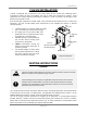
Installation GAS SUPPLY AND GAS PIPE SIZING TO TURN OFF GAS TO APPLIANCE 1. Turn off all electric power to the water heater if service is to be performed. 2. Turn the manual gas valve located on the outside of the unit clockwise 3 to the off position. WARNING • Ensure that any and all gas regulators used are operating properly and providing gas pressures within the specified range shown below. Excess gas inlet pressure may cause serious accidents.
Installation 4. Re‐open the manual gas valve. Check to see that there are no gas leaks. Open some of the fixtures that use the highest flow rate to turn on the T‐H2‐DV/T‐H2‐OS. 5. Check the inlet gas pressure. When T‐H2‐DV/T‐H2‐OS is on maximum burn, the manometer should read from 5.0” to 10.5” WC for Natural gas, from 8.0” to 14.0” WC for Liquid Propane.
Installation Based on Energy Content of 1000BTU/Cubic Ft: Gas Sizing Example (Natural Gas) T‐H2‐DV/ T‐H2‐OS 199,000BTU 5’ Length 1‐1/4” Pipe Size A Dryer 35,000BTU 10’ Length 3/4” Pipe Size 10’ Length 5’ Length 1” Pipe Size 1‐1/4” Pipe Size B 10’ Length 1/2” Pipe Size 15’ Length 1” Pipe Size 10’ Length 3/4” Pipe Size Furnace 120,000BTU Gas Meter Divide each appliance’s BTU requirement by 1000BTU to get the appliances Cubic Ft. requirement.
Installation PRESSURE RELIEF VALVE The T‐H2‐DV/T‐H2‐OS has a high‐temperature shut off switch built in as a standard safety feature (called a Hi‐Limit switch) therefore a “pressure only” relief valve is required. 1. This unit does not come with an approved pressure relief valve. 2. An approved pressure relief valve must be installed on the hot water outlet. 3. The pressure relief valve must conform to ANSI Z21.22 or CAN 1‐4.4 and installation must follow local code. 4.
Installation ‐Condensate Drain Connections‐ • Discharge condensate (acidic water) in accordance with all local codes and WARNING common safety practices. The T‐H2‐DV/T‐H2‐OS are high efficiency condensing water heaters that produce condensate (acidic water). The acidic condensate generated in the secondary heat exchanger can be neutralized by the TH‐ NT01 Neutralizer. Case A: If a neutralizer is not required 1.
Installation • The condensate drain is at atmospheric pressure (non‐pressurized) and therefore must be allowed to drain freely with gravity only. Please ensure that there are no blockages along the condensate drain tube. All portions of the condensate drain (neutralizer and drain tube) must be at a lower elevation than the T‐H2‐DV/T‐H2‐OS to prevent condensate water from building up inside the heat exchanger.
Installation ELECTRICAL CONNECTIONS WARNING CAUTION Follow the electrical code requirements of the local authority having jurisdiction. In the absence of such requirements, follow the latest edition of the National Electrical Code ANSI/NFPA 70 in the U.S. or the latest edition of CSA C22.1 Canadian Electrical Code, Part 1, in Canada. When servicing or replacing parts within the T‐H2‐DV/T‐H2‐OS, label all wires prior to disconnection to facilitate an easy and error‐free reconnection.
Installation TM‐RE30 REMOTE CONTROLLER CONNECTION 1. Disconnect power supply from the T‐H2‐DV/T‐H2‐OS. 2. Take off the T‐H2‐DV/T‐H2‐OS’s front cover. 3. Locate the remote controller terminal, pictured below (located around the upper right‐hand side of the computer board). 4. Open the plastic cover of the TM‐RE30, and then attach the two fork terminals to connector base of the backside the TM‐RE30 with two screws. Make sure the terminals are firmly fixed. 5.
Installation PUMP CONTROL CONNECTION The T‐H2‐DV/T‐H2‐OS can be used to control a recirculation pump. Proper pump control helps to preserve the life of the system and saves energy as well: The T‐H2‐DV/T‐H2‐OS pump control port is a “normally open dry contact”, and therefore needs additional components to properly control a recirculation pump. To control a recirculation pump, connect the pump to the “Pump connector” in the T‐H2‐DV/T‐H2‐OS as shown in the diagram below.
Installation PUMP CONTROL MODES The T‐H2‐DV/T‐H2‐OS provides the four types of the pump control modes. The pump control modes are selected by changing dipswitch settings. The dipswitches that change the pump control modes are located in the right bank of dipswitches in the upper‐ left quadrant of the computer board in the T‐H2‐DV/T‐H2‐OS. (See right.) These 4 modes only affect pumps that are connected to the T‐H2‐DV/T‐H2‐OS pump control (p.25) Right bank of dipswitches A) Recirculation Control: No.
Installation D) Normal Control (Default setting): No.5 and No.6 OFF Feature: This mode provides no special pump control. Pump activation can only be turned ON or OFF by the TM‐RE30 remote controller. Function: The pump will run continually all the time as long as there is a power supply to the T‐H2‐ DV/T‐H2‐OS. The pump will only stop when the TM‐RE30 remote is turned off. Water in the loop will be maintained at the set temperature of the water heater.
Installation EASY‐LINK SYSTEM ‐General‐ The T‐H2‐DV/T‐H2‐OS can be connected with other heaters of the same model with communication cables to work as a multiple‐unit manifold system. • The Easy‐Link system allows up to 4 units to manifold together. • A communication cable (gray color) comes with each unit. You can manifold from 2 to 4 units without the need for a multi‐system controller. A 4‐unit system has full automatic modulation between 13,000 BTU/h and 796,000 BTU/h.
Installation 4. Between the “MASTER” and the “SLAVE‐1” units Connect the “MASTER connector” of the “MASTER” unit to the “[1] connector” of the “SLAVE‐1” unit. 5. Between the “SLAVE‐1” and the “SLAVE‐2” units Connect the “[2] connector” of the “SLAVE‐1” unit to the “[1] connector” of the “SLAVE‐2” unit. 6. Between the “SLAVE‐2” and the “SLAVE‐3” units Connect the “[2] connector” of the “SLAVE‐2” unit to the “[1] connector” of the “SLAVE‐3” unit. 7. Make sure the “3‐digit 7‐seg.
Installation (C) Examples of incorrect settings and/or connections CASE 1: • Unless you change dipswitch No.10 of the “MASTER” unit to the “ON” position, the system will not work as an Easy‐Link system. The units will operate as individual units.
Installation CASE 3: If you connect the “MASTER connector” of the “SLAVE‐1” unit to the “[1] connector” of the “SLAVE‐2” unit, the “SLAVE‐2” unit will operate as an individual unit, and will not be part of the Easy‐Link system.
Applications APPLICATIONS WARNING‐Space‐Heating Applications • In order to purge air in water pipes within a closed‐loop system, an air vent and air separator should be installed in to the system. Required circulation flow rates are labeled next to each application diagram. These flow rate requirements must be followed.
Applications ‐Dual‐purpose hot water heating‐ (Domestic and Space Heating): Diagramatic Layout of Radiant Heating and Domestic Water Heater Per Mass. Code An approved Pressure Only Relief Valve, Tie to Location approved by Local Codes and Must Meet BTU Rating of Takagi Model Used Cold Inlet Apply Correct Thermal Expansion Tank-Size Per Application Shut-Off Valve 4" Gas Exhaust Vent (Discharge Must Comply with Local and State Codes).
Initial Operation INITIAL OPERATION FOR YOUR SAFETY, READ BEFORE OPERATING • Check the GAS and WATER CONNECTIONS for leaks before firing unit for the first time. • Open the main gas supply valve to the unit using only your hand to avoid any spark. Never use tools. If the knob will not turn by hand, do not try to force it; call a qualified service technician. Forced repair may result in a fire or explosion due to gas leaks.
Operating Safety Ow n er’s Gu id e OPERATING SAFETY FOR YOUR SAFETY READ BEFORE OPERATING WARNING: If you do not follow these instructions exactly, a fire or explosion may result causing property damage, personal injury or loss of life. A. This water heater does not have a pilot. It is equipped with an ignition device that automatically lights the burner. Do not try to light the burner by hand. B. BEFORE OPERATING smell all around the water heater area for evidence of leaking gas.
Operating Safety DANGER Vapors from flammable liquids will explode and catch fire causing death or severe burns. Do not use or store flammable products such as gasoline, solvents or adhesives in the same room or area near the water heater. Keep flammable products: 1. Far away from heater. 2. In approved containers. 3. Tightly closed 4. Out of children's reach Vapors: 1. Cannot be seen 2. Vapors are heavier than air 3. Go a long way on the floor 4.
Normal Operation NORMAL OPERATION GENERAL 1. Open a hot water tap. 2. Mix cold water with the hot to get the correct temperature water. 3. Close the hot water tap. • Flow rate to activate the T‐H2‐DV/T‐H2‐OS : 0.5 gallon per minute • Flow rate to keep the T‐H2‐DV/T‐H2‐OS running : 0.4 gallon per minute WARNING WARNING Hot Water temperatures over 125°F can cause severe burns instantly or death from scalding. • The outlet hot water temperature of the T‐H2‐DV/T‐H2‐OS water heater is factory set at 120°F.
Normal Operation Figure.1 Increase button Decrease button 3‐digit 7‐Seg LED T‐H2‐DV/T‐H2‐OS computer board Temperatures available 100 105 110 115 (unit:°F) 120 125 135 140 145 150 155 160 165 170 175 185 • The temperature has been preset at the factory to 120°F (49°C). • If temperatures other than the ones listed above are required, the TM‐RE30 can provide a couple more temperature options. Refer to p. 7 for a list of available temperatures on the TM‐RE30.
Normal Operation FLOW • The flow rate through the T‐H2‐DV/T‐H2‐OS is limited to a maximum of 9.0 GPM. • The temperature setting, along with the supply temperature of the water will determine the flow rate output of the unit. • Please refer to the temperature vs. gallons per minute chart on p. 50 to determine the likely flow rates based on your local ground water temperature and your desired outlet water temperature combination.
Normal Operation MAINTENANCE AND SERVICE Turn off the electrical power supply and close the manual gas control valve and the manual water control valve before servicing. WARNING • Clean the cold‐water inlet filter. (Refer to diagram below) • Be sure that all openings for combustion and ventilation air are not blocked. • Check that the exhaust vent pipe is not blocked. • Check the gas pressure. • Keep the area around the water heater clear.
Troubleshooting TROUBLESHOOTING GENERAL PROBLEM SOLUTIONS It takes long time to get hot water at the fixtures. • The time it takes to deliver hot water from the T‐H2‐DV/T‐H2‐OS to your fixtures depends on the length of piping between the two. The longer the distance or the bigger the pipes, the longer it will take to get hot water. • If you would like to receive hot water to your fixtures quicker, you may want to consider a hot water recirculation system. (p. 32) The water is not hot enough.
Troubleshooting ‐EASY‐LINK SYSTEM‐ ‐TM‐RE30 (OPTIONAL)‐ ‐ WATER HEATER ‐ PROBLEM Unit does not ignite when water goes through the unit. SOLUTIONS • Is the flow rate over 0.5 GPM? (p. 37) • Check for the filter on cold water inlet. (p. 40) • Check for reverse connection and cross connection. • If you use the remote controller, is the power button turned on? The fan motor is still spinning after operation has stopped. • This is normal.
Troubleshooting ERROR CODES T‐H2‐DV/T‐H2‐OS units are self diagnostic for safety and convenience when trouble shooting. • If there is a problem with the installation or the unit, it will display a numerical error code on the 3‐ digit 7‐Seg. LED on the computer board (visible through a window on the front cover) or TM‐RE30 (if installed) to communicate the source of the problem. • Consult the table on the following page for the cause of each error code.
Troubleshooting ‐FAULT ANALYSIS OF ERROR CODES‐ If there is a problem with the installation or the T‐H2‐DV/T‐H2‐OS, it will display a numerical error code on the 7‐seg LED of the computer board or the TM‐RE30 (if installed) to communicate the source of the problem. Error Code Malfunction description Diagnosis Check the dipswitch settings on PCB Call TAKAGI Technical Dept.
Components Diagram COMPONENTS DIAGRAM Case assembly Other than the case assembly (No.15) and front cover (No.16), all of the T‐H2‐OS’s parts are the same as the T‐H2‐DV. The T‐H2‐OS doesn’t have fan motor for exhaust (No.124).
Components Diagram 719 Computer board assembly 055 715 715 Other than Part# 719, the T‐H2‐DV and the T‐H2‐OS share the same components. The T‐H2‐OS doesn’t have exhaust thermistor assembly (No.706) and exhaust fan motor wire (No.720). 712 714 716 053 711 713 053 053 713 055 001 152 701 708 707 717 706 709 705 704 719 423 704:For T-H2-DV 719:For T-H2-OS 711 114 710 720 Burner assembly The T‐H2‐DV and the T‐H2‐OS share the same components.
Components Diagram Water way assembly Other than Part# 456, Part# 459, Part# 460 and Part# 461, the T‐H2‐DV and the T‐H2‐OS share the same components. The T‐H2‐OS doesn’t have hi‐limit switch for exhaust (No.442) and exhaust thermistor assembly (No.706).
Parts List PARTS LIST Item# 001 002 003 004 005 006 007 Part# EKH5B EKH5M EV00K EM335 EKH5D EKJ64 EX13M 008 EM484 009 010 011 012 013 014 015 016 051 052 053 054 055 101 102 103 104 105 106 107 108 109 110 111 112 113 114 116 EKK22 EKH23 EKH5K EKH4G EKH4K EKH73 EKH5C EKH61 EW000 EW002 EX010 EW02B EW023 EKH5W EKK2X EKK0G EKK2V EKK2W EKK0E EKK32 EKK0F EKN61 EKK2M EKH5G EKK2N EKK2D EKK25 EKK2Y Description Case assembly for T‐H2‐DV Front cover for T‐H2‐DV Intake air port assembly Bracket Back guard panel
Parts List Item# 413 414 415 416 417 418 419 420 421 422 423 424 425 426 427 428 429 430 431 432 433 434 435 436 437 438 Part# EX021 EX01H EKK2P EK239 EZF06 EX00H EZF04 EZF16 EKH74 EKK38 EKH32 EW00A EKK27 EKJ47 EW00L EZF15 EKH33 EKH75 EX137 EKN34 EKK2T EKH30 EKJ02 EZH17 EZF14 EKH6H 440 EKH4H 441 442 443 444 445 446 447 EKH4J EKH6G EKK24 EX13H EKH5N EKH6X EKH66 448 EKH78 449 EX13L Description Heater plate Fastener “16AG” Outlet heater Outlet drain plug O‐ring P6 FKM Mixing thermistor O‐ring P4 FKM
Output Temperature Chart OUTPUT TEMPERATURE CHART Temperature vs. GPM (Max. 9.0 GPM) with Various Ground Water Temperature 10.0 9.0 Out Put Hot Water GPM Output Hot Water GPM 8.0 7.0 6.0 5.0 4.0 3.0 2.0 1.0 0.0 100 105 110 115 120 125 130 135 140 150 160 165 170 175 180 185 40 F 6.1 5.6 5.2 4.9 4.6 4.3 4.1 3.8 3.7 3.3 3.0 2.9 2.8 2.7 2.6 2.5 50 F 7.3 6.6 6.1 5.6 5.2 4.9 4.6 4.3 4.1 3.7 3.3 3.2 3.0 2.9 2.8 2.7 60 F 9.0 8.1 7.3 6.6 6.1 5.6 4.8 4.
Warranty WARRANTY Product Registration and Limited Warranty 1. Product registration card or form: The enclosed product registration card must be completed and returned within 45 days of original purchasing date by retail buyer. Copy of proof of original purchasing date must be sent in with the warranty card. The customer may register online with attached proof of original purchasing date via the Internet (www.takagi.com/warranty). THE CARD OR FORM IS FOR PRODUCT REGISTRATION.
Warranty 4. Repair, Replacement or Refund: The manufacturer or its authorized Service Representative will, at its sole discretion, repair or replace any failed or defective mechanical or electrical parts, or components thereof, or, if the manufacturer or its authorized Service Representative cannot replace said parts, and repair is not commercially practicable, the manufacturer or its authorized Service Representative will refund the purchase price.