
Installation Manual

Installation
9│Page
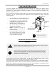
Thedarksquaresindicatethedirectionthe
dipswitchesshouldbesetto.
Leftbankofdipswitches
Leftbankofdipswitches
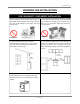
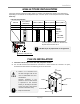
• There is a 3” clearance from
the left and right sides of the
unit to combustible and non‐
combustible
surfaces.However, if any
portion or area of the surface
is exposed to the exhaust
fumes(i.e.directlytothesides
of the vent cap), that surface
mustbeatleast24”
away.
• Keeptheclearances.
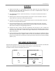
2,500 to4,000 ft
4,000to5,000ft
Altitude
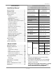
HIGH‐ALTITUDEINSTALLATIONS
Checktheelevationwhereyourwaterheaterisinstalled.Setdipswitchesshowninthetablebelow
dependingonthealtitude.Thesedipswitches(No.5andNo.6)areonthecomputerboardontheleft
bankonly.
0to2,500ft
(DEFAULT)
Over5,000ft
SwitchNo.5 OFF
ON
OFF
Consult
TAKAGI
Technical
Dept.
at1‐888‐
882‐5244
SwitchNo.6
OFF OFF ON
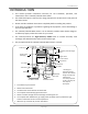
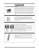
T‐H2‐OSINSTALLATION
1. InstalltheT‐H2‐OSonlyinareaswithmild,temperateclimates.
2. The T‐H2‐OS shall be wall‐mounted or mounted on a stand. Locate the T‐H2‐OS in an open,
unroofedareaandmaintainthefollowingminimumclearances:
DONOTadjustanydipswitchesontherightbank.
1
2
3
4
5
6
7
8
N
O
9
1
0
N
O
1
2
3
4
5
6
7
8
9
1
0
N
O
1
2
3
4
5
6
7
8
9
1
0
Side3”
Top36”
Side3”
Front24”
Bottom12”
Back0.5”