
Installation Guide


POST MOUNT INSTALLATION CONCRETE APPLICATION
CONCRETE ANCHORS:
TAMKO requires the use of the Hilti HIT‑RE 500‑SD adhesive anchoring system in the installation of this post mount.
The anchoring system must be installed in accordance with Hilti HIT‑RE 500‑SD Instructions and ESR‑2322. Concrete
anchors must be installed in dry, normal weight concrete with a specified compressive strength of 2,500 psi to 8,500
psi. In addition, it is the installer's responsibility to ensure that the application and conditions for use of this post mount
are in accordance with the Requirements and Limitations provided in Appendix A of these instructions, and TAM‑RAIL
CCRR‑0118. Failure to correctly anchor the post mount in accordance with the above requirements could result in a
safety hazard.
For more information regarding HIT‑RE 500‑SD adhesive anchoring please contact Hilti at 1‑800‑879‑8000 or visit
www.Hilti.com.
REQUIREMENTS FOR USE WITH TAM-RAIL 6' RAILING KITS
Post Mount
System
Minimum Concrete
Thickness
Minimum Threaded
Rod Embedment
38" 4‑3/4" 3‑1/2"
44" 5‑1/4" 4"
For TAM‑RAIL code compliance information, please see Architectural Testing, Inc. CCRR‑0118 at tamrail.com
TOOLS REQUIRED FOR INSTALLATION:
Tape measure, round steel brush, compressed air, torque wrench, drill, safety glasses, hearing protection, and Hilti MD 2000
or compatible Hilti dispenser.
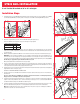
INSTALLATION STEPS:
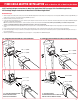
1. Assemble the concrete surface plate to the bottom of the post mount member as shown using four of the supplied 2" coated
hex bolts, 3/8" coated lock washers, and coated 3/8" hex nuts (Fig. 1). Tighten nuts to 33 ft‑lb using a torque wrench. Ensure
that the hex bolt heads are firmly seated inside the surface plate channels.
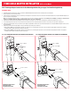
2. Determine the post mount location. Using the 5‑1/2" × 5‑1/2" concrete surface plate as a guide, ensure that the distance
from the edge of the concrete to the edge of the surface plate is at least 4‑1/4". (Fig. 2)
3. Mark the location of the four concrete surface plate corner holes for drilling. (Fig. 2)
IMPORTANT: Before continuing with installation the installer must review and ensure compliance with all Hilti
HIT‑RE 500‑SD instructions and guidelines.
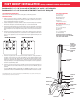
POST MOUNT COMPONENTS:
4" × 4" Post Sleeve (1)
Pyramid Post Cap (1)
New England Post Ring (1)
Post Mount Member (1)
Guide Blocks (2)
1" Stainless Steel Screws (13)
CONCRETE ACCESSORY KIT:
5‑1/2" × 5‑1/2" Concrete Surface Plate (1)
3/8" × 2" Coated Hex Bolts (4)
3/8" Coated Lock Washers (4)
3/8" Coated Hex Nuts (4)
5/16" × 1" Leveling Bolts (4)
3/4" Self‑drilling Guide Block screws (4)
CONCRETE ANCHORING SYSTEM
3/8" × 5‑1/8" Stainless Steel Threaded Rods (4)
3/8" Stainless Steel Washers (4)
3/8" Stainless Steel Nuts (4)
Hilti HIT‑RE 500‑SD Adhesive, 11.1 oz. (1)
(Hilti Dispenser Not Included)
SUBSTITUTION FOR THESE COMPONENTS IS
NOT ALLOWED AS SUBSTITUTING COMPONENTS
COULD CAUSE A SAFETY HAZARD.
FIG. 2
4-1/4" MIN.
4-1/4" MIN.
FIG. 1
BOTTOM OF CONCRETE
SURFACE PLATE
TOP OF CONCRETE
SURFACE PLATE
POST MOUNT MEMBER
CONCRETE
SURFACE PLATE
(See Fig. 4 for
more details)
GUIDE BLOCK
Post Mount Kit 4" x 4" x 38" for use with all TAM‑RAIL
®
6' x 36" Railing Kits
Post Mount Kit 4" x 4" x 44" for use with all TAM‑RAIL
®
6' x 42" Railing Kits
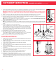
4. Drill four boreholes into the concrete to the required embedment depth using a hammer drill and 7/16" masonry drill bit. When
drilling, check periodically to ensure boreholes remain plumb and aligned with all four of the concrete surface plate corner
holes.
REQUIRED EMBEDMENT DEPTH FOR THREADED RODS:
TAM‑RAIL 38" Post Mount Kits: 3‑1/2"
TAM‑RAIL 44" Post Mount Kits: 4"
5. Properly clean all boreholes using a 7/16" round steel brush and compressed air (see Hilti HIT‑RE 500‑SD Instructions, Steps
2‑4). Boreholes must be free of dust, debris, ice, oil, grease and other contaminants.
6. Prepare the HIT‑RE 500‑SD adhesive for use with a compatible Hilti dispenser and discard initial adhesive (see Hilti HIT‑RE
500‑SD Instructions, Steps 5‑8).
7. Inject adhesive into the boreholes without forming air voids, starting from the bottom of each borehole and slowly withdrawing
the dispenser. Fill holes approximately 2/3 full or as required to ensure that the annular gap between the threaded rod and
concrete is completely filled (see Hilti HIT‑RE 500‑SD Instructions, Steps 9‑10).
Fig. 1 Fig. 2
7