
Installation Guide


Important Product Safety and Pre-Installation Information
The following installation instructions are provided to guide you through the installation process of the Tam‑Rail® Railing System. TAMKO® Building Products, Inc. shall not be
held liable for improper or unsafe installations. Failure to follow these instructions may lead to an unsafe product and will adversely affect coverage under the Limited Warranty.
TAMKO recommends that all designs be reviewed by a licensed architect, engineer or local building official before installation to ensure that they are safe and in
compliance with local building code requirements.
Fire and other sources of excessive heat may damage Tam‑Rail Railing. Damage caused by fire or other heat sources may include melting, sagging, warping, discoloration,
charring, increased expansion or contraction, accelerated weathering, etc.
Low‑E glass is one potential source of excessive heat because it is designed to reflect more sunlight than traditional glass. This enhanced reflectivity combined with any
irregularity in the window glass can concentrate sunlight onto the railing and cause heat build‑up on areas of the railing surface. When this occurs, damage of Tam‑Rail Railing
is possible. Contact the manufacturer of the product which contains the Low‑E glass for suggestions to reduce or eliminate the reflected heat.
A railing system which has been damaged or exhibits signs of excessive wear or weakness must be replaced or repaired immediately as it may be a safety hazard.
Composite railing will retain heat when exposed to direct or reflected sunlight. Exercise caution around these heated surfaces.
Before You Begin:
Kit Contents
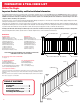
Straight Rail Kits:
TAM‑RAIL Top Rail (6’, 8’, or 10’)
TAM‑RAIL Bottom Rail (6’, 8’, or 10’)
Square or Colonial Balusters (6’=14; 8’=19; 10’=24)
Top Rail Metal Brackets (2)
Bottom Rail Metal Brackets (2)
Top Rail Bracket Covers (2)
Bottom Rail Bracket Covers (2)
1” Stainless Screws (13)
2” Stainless Screws (13)
Crush Block (6' & 8'=1; 10'=2)
Bracket Placement Template (on box)
TABLE OF CONTENTS
Straight Rail ..................................... 3
Stair Rail .......................................... 4
Wood/Composite Post Mount ............ 6
Concrete Post Mount ........................ 7
Fixed Angle Bracket Adapter ............ 9
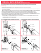
TOP RAIL BRACKET COVER
SQUARE BALUSTER
TOP RAIL
BOTTOM RAIL BRACKET COVER CRUSH BLOCK BOTTOM RAIL
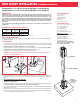
TOP RAIL
BOTTOM RAIL
BRACKET COVER
BOTTOM RAIL
CRUSH BLOCK
SQUARE BALUSTER
TOP RAIL
BRACKET
COVER
Stair Rail Kits:
TAM‑RAIL Top Rail (6’ or 8’)
TAM‑RAIL Bottom Rail (6’ or 8’)
Square or Colonial Balusters (6’=11; 8’=15)
Top Rail Metal Brackets (2)
Bottom Rail Metal Brackets (2)
Top Rail Bracket Covers (2)
Bottom Rail Bracket Covers (2)
1” Stainless Screws (13)
2” Stainless Screws (13)
Crush Block (6'=0; 8'=1)
Wood/Composite and Concrete Post Mount Kits:
See pages 6 ‑ 7
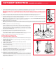
45° Fixed Angle Adapter Kit:
Top Rail Angle Adapter (1)
Bottom Rail Angle Adapter (1)
Note: No hardware is included in the
45° Fixed Angle Adapter Kit as the hardware
from the Tam‑Rail Straight Rail Kit is used.
Tools Required for Installation
Tape measure, miter saw or hack saw, drill, #2 square drive bit, level, pencil, safety glasses, and hearing
protection. For larger construction projects, a miter saw and drill are strongly recommended for quicker
installation.
Note: Some specific tools are required to install the Tam‑Rail Wood/Composite and Concrete Post Mount
Kits. Please see pages 6 –8 for full details.
SUBSTITUTION FOR THESE COMPONENTS IS NOT ALLOWED AS SUBSTITUTING
COMPONENTS COULD CAUSE A SAFETY HAZARD.
22.5° Fixed Angle Adapter Kit:
Top Rail Angle Adapter (1)
Bottom Rail Angle Adapter (1)
#10 × 1‑3/4” screws (5)
#10 × 3” self‑drilling screws (3)
PREPARATION & TOOL CHECK LIST
2