OPERATOR'S MANUAL Model 430 Torque Shake/Slush Freezer Original Operating Instructions 051430-M 3/97 Original Publication (Updated 9/2/14)
Complete this page for quick reference when service is required: Taylor Distributor: Address: Phone: Service: Parts: Date of Installation: Information found on data plate: Model Number: Serial Number: Electrical Specs: Voltage Cycle Phase Maximum Fuse Size: Amps Minimum Wire Ampacity: Amps Part Number: E 1997 Carrier Commercial Refrigeration, Inc.
Table of Contents Section 1 To the Installer . . . . . . . . . . . . . . . . . . . . . . . . . . . . . . . . . . . . . . . . . . . . 1 Installer Safety . . . . . . . . . . . . . . . . . . . . . . . . . . . . . . . . . . . . . . . . . . . . . . . . . . . . . . . . 1 Site Preparation . . . . . . . . . . . . . . . . . . . . . . . . . . . . . . . . . . . . . . . . . . . . . . . . . . . . . . . 1 Air Cooled Units . . . . . . . . . . . . . . . . . . . . . . . . . . . . . . . . . . . . . . . . . . . . . . .
Table of Contents - Page 2 ______________________________________________________________________________ Section 7 Important: Operator Checklist . . . . . . . . . . . . . . . . . . . . . . . . . . . . . . 18 During Cleaning and Sanitizing: . . . . . . . . . . . . . . . . . . . . . . . . . . . . . . . . . . . . . . . . . 18 Troubleshooting Bacterial Count: . . . . . . . . . . . . . . . . . . . . . . . . . . . . . . . . . . . . . . . . 18 Regular Maintenance Checks: . . . . . . . . . . . . . . . . .
Section 1 To the Installer The following information has been included in the manual as safety and regulatory guidelines. For complete installation instructions, please see the Installation Checklist. This unit has many sharp edges that can cause severe injuries. Installer Safety Site Preparation In all areas of the world, equipment should be installed in accordance with existing local codes. Please contact your local authorities if you have any questions.
Air Cooled Units Each unit requires one power supply for each data label on the unit. Check the data label(s) on the freezer for branch circuit overcurrent protection or fuse, circuit ampacity, and other electrical specifications. Refer to the wiring diagram provided inside of the electrical box for proper power connections. DO NOT obstruct air intake and discharge openings: Air cooled units require a minimum of 3” (76.
Beater Rotation Refrigerant liquid sprayed onto the skin may cause serious damage to tissue. Keep eyes and skin protected. If refrigerant burns should occur, flush immediately with cold water. If burns are severe, apply ice packs and contact a physician immediately. Beater rotation must be clockwise as viewed looking into the freezing cylinder. Note: The following procedure must be performed by an authorized Taylor service technician.
Section 2 To the Operator The freezer you have purchased has been carefully engineered and manufactured to give you dependable operation. The Taylor Model 430 Torque, when properly operated and cared for, will produce a consistent quality product. Like all mechanical products, they will require cleaning and maintenance. A minimum amount of care and attention is necessary if the operating procedures outlined in this manual are followed closely.
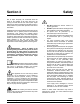
Section 3 Safety We, at Taylor Company, are concerned about the safety of the operator at all times when they are coming in contact with the unit and its parts. Taylor makes every effort to design and manufacture built- in safety features to protect both operators and service technicians. S S Installing and servicing refrigeration equipment can be hazardous due to system pressure and electrical components.
This unit is provided with an equipotential grounding lug that is to be properly attached to the rear of the frame by the authorized installer. The installation location is marked by the equipotential bonding symbol (5021 of IEC 60417-1) on both the removable panel and the equipment’s frame. Cleaning and sanitizing schedules are governed by your state or local regulatory agencies and must be followed accordingly.
Section 4 Operator Parts Identification 9 8 10 7 12 6 11 AUTO OFF WASH 5 1 2 3 Item Description Part Number Item 4 Description Part Number 1 Shield- Splash 049320 7 Panel- Side Left 049639 2 Tray- Drip 049319 8 Tube- Feed 13/32 Hole 025663- 10 3 Pan- Drip 17- 1/4” Long 027504 9 Cover A.- Black Insulated X49679- BLA 4 Gasket- Base Pan 049420 10 Panel- Back 049325 5 Panel A.
Item Description Part Number Item Description Part Number *1 Door A.- Partial X39248- SER 11 Bearing- Front 013116 2 Handle A.- Draw X47384 12 Beater A.- 4 Qt. 1 Pin Support X49490 3 Valve- Draw 047734 13 Blade- Scraper- Plastic 046237 4 Valve A.- Handle Pin X25929 14 Clip- Scraper Blade 046238 5 O- Ring - 1” OD x .139 W 032504 15 Shaft- Beater 035418 6 Buster- Ice 047735 16 Seal- Drive Shaft 032560 7 O- Ring - .291 ID x .080 W 018550 17 O- Ring 7/8 OD x .
Item Description Part Number 1 Brush- 3” x 7” White 023316 2 Brush- Double Ended 3 Brush- Draw Valve Item Description Part Number 4 Brush- Rear Bearing 013071 013072 5 Lubricant- Taylor 047518 014753 *6 Video- Training M430Torque 050987- DVD *Not Shown.
Section 5 Important: To the Operator Viscosity Adjustment Reset Button The viscosity (thickness) of the slush can be adjusted by turning the viscosity adjustment screw on the upper right side of the front panel. Turn the viscosity adjustment screw clockwise for a thicker product, or counterclockwise for a thinner product. After making an adjustment, allow the refrigeration system to cycle 2 or 3 times to accurately evaluate the viscosity. The reset button is located in the rear panel.
Section 6 Operating Procedures The Model 430 freezer is designed to produce shake or slush product at the desired thickness. This unit has a 4 quart freezing cylinder. Insert the beater drive shaft into the rear shell bearing and engage the square end firmly into the female socket of the drive unit. Be certain that the drive shaft fits into the drive coupling without binding.
Holding the beater securely, slide the beater into the freezing cylinder and align the hole at the rear of the beater with the flats on the end of the drive shaft. Slide the beater the remainder of the way into the freezing cylinder and over the end of the drive shaft. The beater assembly will not protrude beyond the front of the freezing cylinder. Figure 9 Step 5 Assemble the freezer door with the “Ice Buster” (door spout clearing device).
Place the large rubber gasket into the groove on the back side of the freezer door. Slide the white, plastic front bearing onto the bearing hub, making certain that the flanged end of the bearing is resting against the freezer door. DO NOT lubricate the door gasket or front bearing. Rotate the draw valve so the flats on the top of the draw valve are perpendicular to the door face. Figure 12 Insert the ice buster through the door spout and into the slot located just above the lower o- ring.
Sanitizing Step 7 Install the front drip pan. Slide the long drip pan into the hole in the front panel. Step 1 Prepare a pail of an approved 100 PPM sanitizing solution (examples: 2- 1/2 gal. [9.5 liters] of Kay- 5R or 2 gal. [7.6 liters] of Stera- SheenR). USE WARM WATER AND FOLLOW THE MANUFACTURER’S SPECIFICATIONS. Step 2 Pour the sanitizing solution into the hopper and allow it to flow into the freezing cylinder. Figure 17 Step 8 Install the front drip tray and splash shield beneath the door spout.
Priming Step 5 Place an empty pail beneath the door spout and move the draw handle to the right. Draw off all the sanitizing solution. When the sanitizer stops flowing from the door spout, move the draw handle to the left and place the control switch in the “OFF” position. Step 1 With a pail beneath the door spout, move the draw handle to the right. Pour two gallons (7.6 liters) of FRESH mix into the hopper and allow it to flow into the freezing cylinder.
Step 4 Place the mix hopper cover in position. Periodically, during the day’s operation, check to be sure there is a substantial amount of mix in the hopper. Note: If local health codes DO NOT permit the use of rerun, the product must be discarded. Follow the instructions in the previous step, except drain the product into a pail and properly discard the mix. ALWAYS FOLLOW LOCAL HEALTH CODES. Rinsing Step 1 Pour two gallons (7.6 liters) of cool, clean water into the mix hopper.
Cleaning Brush Cleaning Step 1 Prepare a sink with a cleaning solution (examples: Kay- 5R or Stera- SheenR). USE WARM WATER AND FOLLOW THE MANUFACTURER’S SPECIFICATIONS. (If another approved cleaner is used, dilute according to label instructions. IMPORTANT: Follow the label directions. Too STRONG of a solution can cause parts damage, while too MILD of a solution will not provide adequate cleaning.) Make sure all brushes provided with the freezer are available for brush cleaning.
Section 7 Important: Operator Checklist During Cleaning and Sanitizing: the rerun with fresh mix in a ratio of 50/50 during the day’s operation. j 6. On a designated day of the week, run the mix as low as feasible and discard after closing. This will break the rerun cycle and reduce the possibility of high bacteria and coliform counts. ALWAYS FOLLOW LOCAL HEALTH CODES j 7. Properly prepare the cleaning and sanitizing solutions. Read and follow label directions carefully.
Winter Storage Wrap detachable parts of the freezer such as beater, blades, drive shaft, and freezer door, and place in a protected dry place. Rubber trim parts and gaskets can be protected by wrapping with moisture- proof paper. All parts should be thoroughly cleaned of dried mix or lubrication accumulations which attract mice and other vermin.
Section 8 PROBLEM 1. No product being dispensed. 2. Unit will not operate in the “AUTO” or “WASH” mode. 3. No compressor operation in the “AUTO” mode. 4. Product too thick. Troubleshooting Guide Troubleshooting Guide PROBABLE CAUSE REMEDY PAGE REF. a. Power switch is in the “OFF” position. a. Place power switch in the “AUTO” position. 15 b. Improper mixing of product. b. Carefully follow directions for mixing product. - - - c. Inadequate mix in hopper. c. Fill hopper with mix. 16 d.
PROBLEM 5. Product too thin. 6. Scored walls of freezing cylinder. 7. Excessive leakage into rear drip pan. 8. Excessive leakage from door spout. 9. Unable to remove drive shaft. Model 430 Torque PROBABLE CAUSE REMEDY PAGE REF. a. Missing, incorrectly installed, or bad scraper blade. a. Install or replace scraper blade. 11 b. Improper mixing of product. b. Carefully follow directions for mixing product. - - - c. The viscosity adjustment is set incorrectly. c. Adjust accordingly. d.
Section 9 PART DESCRIPTION Parts Replacement Schedule EVERY 3 MONTHS EVERY 6 MONTHS ANNUALLY QUANTITIES TO BE REPLACED Drive Shaft Seal X 1 Drive Shaft O- Ring X 1 Scraper Blade X 1 Freezer Door Gasket X 1 Front Bearing X 1 Draw Valve O- Rings X 2 Black Bristle Brush - 1” x 2” Inspect & Replace if Necessary Maximum 1 White Bristle Brush - 1- 1/2” x 2” Inspect & Replace if Necessary Maximum 1 White Bristle Brush - 3” x 7” Inspect & Replace if Necessary Maximum 1 Refer to th
Section 10 Limited Warranty on Equipment TAYLOR COMPANY LIMITED WARRANTY ON FREEZERS Taylor Company, a division of Carrier Commercial Refrigeration, Inc. (“Taylor”) is pleased to provide this limited warranty on new Taylor-branded freezer equipment available from Taylor to the market generally (the “Product”) to the original purchaser only. LIMITED WARRANTY Taylor warrants the Product against failure due to defect in materials or workmanship under normal use and service as follows.
3. Replacement of wear items designated as Class “000” parts in the Taylor Operator’s Manual. 4. External hoses, electrical power supplies, and machine grounding. 5. Parts not supplied or designated by Taylor, or damages resulting from their use. 6. Return trips or waiting time required because a service technician is prevented from beginning warranty service work promptly upon arrival. 7.
Section 11 Limited Warranty on Parts TAYLOR COMPANY LIMITED WARRANTY ON TAYLOR GENUINE PARTS Taylor Company, a division of Carrier Commercial Refrigeration, Inc. (“Taylor”) is pleased to provide this limited warranty on new Taylor genuine replacement components and parts available from Taylor to the market generally (the “Parts”) to the original purchaser only. LIMITED WARRANTY Taylor warrants the Parts against failure due to defect in materials or workmanship under normal use and service as follows.
LIMITED WARRANTY EXCEPTIONS This limited warranty does not cover: 1. Labor or other costs incurred for diagnosing, repairing, removing, installing, shipping, servicing or handling of defective Parts, replacement Parts, or new Parts. 2. Normal maintenance, cleaning and lubrication as outlined in the Taylor Operator’s Manual, including cleaning of condensers or carbon and grease buildup. 3.
LIMITATION OF WARRANTY THIS LIMITED WARRANTY IS EXCLUSIVE AND IS IN LIEU OF ALL OTHER WARRANTIES, CONDITIONS AND/OR REMEDIES UNDER THE LAW, INCLUDING ANY IMPLIED WARRANTIES OR CONDITIONS OF MERCHANTABILITY OR FITNESS FOR A PARTICULAR PURPOSE. THE ORIGINAL OWNER’S SOLE REMEDY WITH RESPECT TO ANY PRODUCTS SHALL BE REPAIR OR REPLACEMENT OF DEFECTIVE PARTS UNDER THE TERMS OF THIS LIMITED WARRANTY.
BLK BLK BLK BLU MIX OUT LAMP AUTO WASH AUTO WASH ORG BLK/WHT OFF OFF NO C C NO L1 BLK/WHT BRN/WHT BLK/WHT WHT/ORN WHT BLK T1 BLK BLK BLK LINE ORG WHT BLK BRN/WHT A1 GRN/YEL BLK BEATER MOTOR STARTER COIL M SPINNER A2 BLK L1 WHT WHT WHT WHT SPINNER SWITCH NC 45° LOCKOUT-INSTALL JUMPER TO ENABLE (REQUIRES OPTIONAL DOOR SWITCH) JUMPER FUNCTION NO NO JUMPER FACTORY INSTALLED NO PINS 1&2 REFRIGERATION INTERVAL. NO JUMPER = 7 MINUTES, JUMPER INSTALLED = 12 MINUTES.
BLK BLK BLK MIX OUT PROBE BLK BLK 6 2 COMPRESSOR HIGH PRESSURE LIMIT SWITCH 1 J1 J2 1 2 3 4 5 6 7 W2 W1 BLK BLU MIX OUT LAMP WASH AUTO WASH AUTO POWER SWITCH CLEAN REQ'D LAMP(OPTIONAL) WHT WHT ADD MIX LAMP 1 2 3 4 5 6 7 8 J3 TORQUE CONTROL F1 ORG BLK/WHT OFF OFF NC NO YEL SET SWITCH TO 240V 115V 240V C0M BLU NO C C NO L1 T1 BLK WHT WHT/ORN BRN/WHT BLK/WHT ORG COMPRESSOR CONTACTOR BLK BLK ORG BLK BRN/WHT A1 BLK BEATER MOTOR STARTER COIL M SPINNER A2 BLK