MotorGuard KMG High Performance Output Sine Wave Filter Installation, Operation, and Maintenance Manual
™ MotorGuard KMG High Performance Output Sinewave Filter Installation, Operation, and Maintenance Manual TCI, LLC W132 N10611 Grant Drive Germantown, Wisconsin 53022 Phone: 414-357-4480 Fax: 414-357-4484 Helpline: 800-TCI-8282 Web Site: http://www.transcoil.
Table of Contents Safety Instructions ........................................................................................ 5 Overview ................................................................................................................................................. 5 Warnings and Cautions ......................................................................................................................... 5 General Safety Instructions ....................................................
Start Up (Commissioning) ................................................................................................................... 24 Operation .............................................................................................................................................. 24 Maintenance and Service ........................................................................... 25 MotorGuard Reliability and Service Life ....................................................................
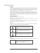
Safety Instructions Overview This section provides the safety instructions which must be followed when installing, operating and servicing the KMG MotorGuard Filter. If neglected, physical injury or death may follow, or damage may occur to the MotorGuard or equipment connected to the MotorGuard. The material in this chapter must be read and understood before attempting any work on, or with, the product. The MotorGuard is intended to be connected to the output terminals of a variable frequency drive (VFD).
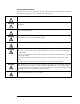
General Safety Instructions These safety instructions are intended for all work on the MotorGuard. Additional safety instructions are provided at appropriate points on other sections of this manual. Warning Be sure to read, understand, and follow all safety instructions. ! Warning Only qualified electricians should carry out all electrical installation and maintenance work on the MotorGuard.
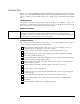
Introduction Thank you for selecting the KMG MotorGuard High Performance Output Filter. TCI has produced this filter for use in many PWM variable frequency drive (VFD) applications that require low distortion sine wave output power. This manual describes how to install, operate, and maintain the MotorGuard filter. Intended Audience This manual is intended for use by all personnel responsible for the installation, operation, and maintenance of the MotorGuard.
Receiving Inspection and Storage Receiving Inspection The MotorGuard has been thoroughly inspected and functionally tested at the factory and carefully packaged for shipment. When you receive the unit, you should immediately inspect the shipping container and report any damage to the carrier that delivered the unit. Verify that the part number of the unit you received is the same as the part number listed on your purchase order.
Product Description MotorGuard Sine Wave Filter The MotorGuard is a low-pass sine wave filter designed and developed by TCI to deliver conditioned power to motor loads driven by PWM drives at a variety of lead lengths. The MotorGuard is available for 460/480 volt and 575/600 volt systems. The MotorGuard is a passive filter connected in series with the output terminals of the variable frequency drive. It is designed to remove the carrier frequency distortion from the output voltage waveform.
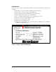
Nameplate Data Figure 1 shows an example of a MotorGuard nameplate. The following information is marked on the nameplate: ♦ Part number: encoded model number explained on the following page ♦ FLA: the rated continuous operating current (RMS amps) ♦ System Voltage: the maximum VFD output voltage (fundamental) ♦ Hz: the maximum VFD output frequency (fundamental) ♦ Phase: 3 – The MotorGuard is designed for use only with 3 phase motors.
Model Number Encoding Figures 2a and 2b identify the significance of each character in the MotorGuard model number. The example model number, KMG130A01A designates an Industrial MotorGuard that is rated 130 amps, 480 volts, and is furnished in a NEMA 1 enclosure.
Standard Product Ratings and Dimension Tables The following tables list the ratings and dimensions of the standard MotorGuard models: ♦ Table 1 lists 480 Volt models on open panels. ♦ Table 2 lists 480 Volt models in NEMA 1 enclosures. ♦ Table 3 lists 600 Volt models on open panels. ♦ Table 4 lists 600 Volt models in NEMA 1 enclosures. ♦ Table 5 lists 480 Volt models in NEMA 1 enclosures. ♦ Table 6 lists 480 Volt models in NEMA 3R enclosures.
Table 1 – Industrial 480 Volt Models on Open Panels Model Number Nominal Horspower Current Rating (amps) Heat Loss (Watts) Weight (lbs.) KMG8A00A KMG12A00A KMG16A00A KMG23A00A KMG30A00A KMG35A00A KMG45A00A KMG55A00A KMG65A00A KMG80A00A KMG110A00A KMG130A00A KMG160A00A KMG200A00A KMG250A00A KMG305A00A KMG362A00A KMG420A00A KMG480A00A KMG600A00A KMG750A00A 5 7.
Table 3 – Industrial 600 Volt Models on Open Panels Model Number Nominal Horspower Current Rating (Amps) Heat Loss (Watts) Weight (lbs.) KMG8C00A KMG10C00A KMG12C00A KMG20C00A KMG25C00A KMG28C00A KMG35C00A KMG45C00A KMG55C00A KMG65C00A KMG80C00A KMG110C00A KMG130C00A KMG160C00A KMG200C00A KMG250C00A KMG305C00A KMG362C00A KMG420C00A KMG500C00A KMG600C00A 5 7.
Table 5 – General Purpose 480 Volt Models in NEMA 1 Enclosures Model Number Nominal Horspower Current Rating (Amps) Weight (lbs.) KMG55AG010000 KMG65AG010000 KMG80AG010000 KMG110AG010000 KMG130AG010000 KMG160AG010000 KMG200AG010000 KMG250AG010000 KMG305AG010000 KMG362AG010000 KMG420AG010000 KMG480AG010000 KMG600AG010000 40 50 60 75 100 125 150 200 250 300 350 400 500 55 65 80 110 130 160 200 250 305 362 420 480 600 209 215 235 220 225 250 260 595 625 630 635 635 755 Height (in.) Width (in.
Table 7 – General Purpose 600 Volt Models in NEMA 1 Enclosures Model Number Nominal Horspower Current Rating (Amps) KMG45CG010000 KMG55CG010000 KMG65CG010000 KMG80CG010000 KMG110CG010000 KMG130CG010000 KMG160CG010000 KMG200CG010000 KMG250CG010000 KMG305CG010000 KMG362CG010000 KMG420CG010000 KMG500CG010000 KMG600CG010000 40 50 60 75 100 125 150 200 250 300 350 400 500 600 45 55 65 80 110 130 160 200 250 305 362 420 500 600 Weight (lbs.) 209 235 235 266 275 280 290 570 615 620 650 675 810 Height (in.
Product Technical Specifications Tables 9a, 9b, 10a, and 10b list the major technical specifications for the MotorGuard product line. Table 9a – MotorGuard Technical Specifications – Industrial Current ratings Continuous current: 8 to 750 amps.
Table 10a – MotorGuard Technical Specifications – General Purpose Current ratings Continuous current: 55 to 600 amps. See Rating and Dimension tables Intermittent current: 150% for 1 minute out of every 60 minutes VFD Drive output voltage 460/480 and 575/600 V, 3 ph, at fundamental base frequency VFD Drive output frequency 0 to 80 Hz VFD Drive carrier frequency 2 kHz and 12 kHz, Ideally 4 kHz to 8 kHz Control power input For fan operation.
Pre-installation Planning Verify the Application MotorGuard Ratings Make sure that the MotorGuard is correct for the application. The voltage and current ratings of the MotorGuard must match the output voltage and current ratings of the connected variable frequency drive as it is configured for use with the connected motor.
Power Wiring The conduit and wiring from the output of the variable frequency drive to the motor must be routed to the MotorGuard and then to the motor. When selecting a mounting location for the MotorGuard, plan for the routing of the power wiring. Control Wiring (for units with boards) Control Power The MotorGuard requires 120 VAC single-phase power for the monitor board and cooling fan. The control power source must be ensured to be energized whenever the variable frequency drive is operating.
Installation Guidelines Mounting The MotorGuard must be mounted vertically on a smooth, solid surface, free from heat, dampness, and condensation. Wiring Cable Entry Locations ↓(Lifting eye is optional) Figure 3 – Cable Entry Location for General Purpose units Field Wiring Connection Terminals Compression type terminals may be provided for all field wiring connections. The control circuit terminals will accommodate 18 AWG to 10 AWG wire and should be tightened to 18 in.-lbs. torque.
Table 11 – Motor Power Terminal Wire Size Capacity Range and Tightening Torque (Cu or Al) - Industrial Ground Lug KMG IND Model Numbers Input and Output Motor Power Wire Size Torque (in.-lb.) Wire Size Torque (in.-lb.
L1(R) Ext Fault Input L2(S) L3(T) G Variable Frequency Drive (U)T1 U (V)T2 V (W)T3 W G G 6 7 8 L1 L2 Control T1 Power Fault T2 Output MotorGuard T3 T1 T2 Motor T3 G Figure 4 – Typical Connection Diagram Grounding The MotorGuard panel equipment grounding lug must be connected to the ground of the premises wiring system. The equipment grounding connection must conform to the requirements of the National Electric Code (NEC) and/or any other codes that apply to the installation site.
MotorGuard Operation Adjustments Monitor Board Settings (for units with boards) The monitor board configuration switches are factory set and should not be changed. The monitor board component layout is shown in Figure 5 in the Maintenance and Service section on a following page. Make sure that the configuration switches are set as follows: ♦ For 480 volt models: Set all sections of S1 to ON. Alarm level dv/dt = 1000 V/μs.
Maintenance and Service MotorGuard Reliability and Service Life The MotorGuard has been designed to provide a service life that equals or exceeds the life of the variable frequency drive. It has been thoroughly tested at the factory to ensure that it will perform reliably from the moment it is put into service. The following periodic maintenance is recommended to ensure that the MotorGuard will always perform reliably and provide the expected service life.
Troubleshooting Only qualified electricians should carry out all electrical installation and maintenance work on the MotorGuard. Disconnect all sources of power to the VFD and MotorGuard before working on the equipment. Do not attempt any work on a powered MotorGuard. Monitor Board (for units with boards) Figure 5 shows the component layout of the monitor board. The monitor board contains the fault alarm relay and the status lights which are described below.
Status Lights (for units with LEDs) During normal operation, both the green LED and the yellow LED are illuminated. The green LED indicates that control power is applied to the monitor board. The yellow LED indicates that the fault relay is energized. If the green LED is not illuminated, possible causes include: ♦ The source of control power is shut off. ♦ A fuse or other protective device external to the MotorGuard has interrupted control power.
Fuses Table 12 lists the specifications for the RC power circuit fuses in the MotorGuard. Table 12 – RC Power Circuit Fuses for Industrial Model 480 V Models 600 V Models Power Circuit Fuse Rating MotorGuard Rating (Amps) Amps 8 12 16 23 30 35 45 55 65 80 110 130 160 200 250 305 362 420 480 600 750 2 2.
typical waveform at the terminals of a motor located a distance away from the VFD. This waveform has voltage peaks of 1500 volts or higher due to the voltage spikes caused by the reflected wave phenomenon. Figure 6 VFD Output Voltage Waveform Motor Voltage Waveform With Reflected Voltage Spikes Filter Output Performance Figure 7 shows the voltage waveform at the output of the MotorGuard or at the terminals of a motor connected to the MotorGuard.
Drawings Typical Isometric Drawings and Schematic Diagrams Typical MotorGuard drawings are provided on the following pages. These drawings provide general information describing your MotorGuard filter. More specific information is provided by the drawings shipped with the unit. Be sure to carefully review the information provided by these drawings. This information takes precedence over the information provided in this manual.
KMG – Capacitor connection may be WYE, consult factory 31
KMG 32
KMG with Board Option 33
KMG with Board Option 34
KMG GP NEMA 3R – Small enclosure KMG GP NEMA 3R – Large enclosure 35
KMG Industrial Filter Open – Small enclosure 36
KMG Industrial Filter Open – Medium enclosure 37
KMG Industrial Filter Open – Large enclosure 38
KMG Industrial Filter Type 1 enclosure – Small enclosure 39
KMG Industrial Filter Type 1 enclosure – Medium enclosure 40
KMG Industrial Filter Type 1 enclosure – Large enclosure 41
KMG Industrial Filter with Monitor Board Option (Shown in a small enclosure) 42
TCI, LLC W132 N10611 Grant Drive Germantown, WI 53022 Phone: 414-357-4480 Fax: 414-357-4484 Helpline: 800-TCI-8282 Web Site: http://www.transcoil.com Publication No. 24362 Version 1.