
Instructions

----- 5 -----
Configuration via DIP switches and jumpers if it is required to switch between
multiple measurement modes via an external switch (Save mode)
The required measurement modes are configured and saved sequentially.
1. Connect supply voltage.
2. Set DIP-switch 10, 11 and 12 to OFF position.
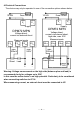
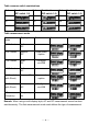
3. Set the measurement mode with jumpers at J4-J6 according to table
"Measurement mode”, column “Save mode".
4. Set DIP switch 10 to ON position.
5. Set upper scale caption for the first measurement mode with DIP switches 1-9
(see “Configuration of the upper scale caption”).
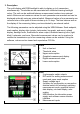
6. Set time base for graphical historic data display (optional, see “Other settings”).
7. Set DIP switch 10 to OFF position.
8. "Saved” appears on the display. The configuration of the first measurement mode
is now completed.
9. When using multiple measurement modes repeat steps 2-8 until all required
measurement modes are configured. The time base must not be set again, as it is
used for all measurement modes.
10. In operation the measuring modes can be changed with a switch at J4-J6
according to table "Measurement mode”, column “Save mode".
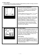
Configuration of the upper scale caption
The upper scale caption is binary coded using DIP switches 1-9. Possible values are 1
to 500. Switch 1 corresponds to 256, switch 2 corresponds to 128, switch 3
corresponds to 64, etc., switch 9 corresponds to 1. For configuration, proceed as
follows:
1. Connect supply voltage.
2. Set DIP switch 10 to ON Position.
3. Set DIP switches 1-9 to OFF position.
4. Start with 1st switch.
5. Set switch to ON position.
6. If the displayed value is greater than the desired value, set the switch back to OFF
position.
7. If the displayed value is less than the desired value, leave switch to ON position
and move on to the next switch.
8. Repeat steps 5 to 7 until desired value is displayed.