
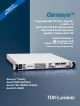
Datasheet

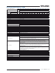
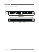

Front Panel Description
1. ON/OFF Switch
2. Air Intake allows zero stacking for maximum system flexibility and power density.
3. Reliable encoder controls Output Voltage, Address, OVP and UVL settings.
4. Volt Display shows Output Voltage and directly displays OVP, UVL and Address settings.
5. Reliable encoder controls Output Current, sets baudrate and Advanced Parallel mode.
6. Current Display shows Output Current and displays Baud rate. Displays total current in Parallel Master/Slave Mode
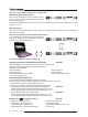
7. Function/Status LEDs:
8. Pushbuttons allow flexible user configuration
8. Pushbuttons allow flexible user configuration
• Coarse and Fine adjustment of Output Voltage/Current and Advanced Parallel Master or Slave select.
• Preview settings and set Voltage/Current with Output OFF, Front Panel Lock
• Parallel Master/Slave
• Set OVP and UVL Limits
• Set Current Foldback Protection
• Go to Local Mode and select Address and Baud rate
• Output ON/OFF and Auto-Re-Start/Safe-Start Mode
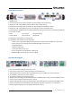
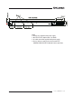
Rear Panel Description
1. Remote/Local Output Voltage Sense Connections.
2. DIP Switches select 0-5V or 0-10V Programming and other functions.
3. DB25 (Female) connector allows (Non-isolated) Analog Program and Monitor and other functions.
4. RS-485 OUT to other Genesys™ Power Supplies.
5. RS-232/RS-485 IN Remote Serial Programming.
6.
Output Connections: Rugged busbars (shown) for up to 100V Output; wire clamp connector for Outputs >100V.
7. Exit air assures reliable operation when zero stacked.
8.
Input: 230VAC Single Phase (shown), 208 VAC Three Phase, 50/60 Hz AC Input Connector: Phoenix P/N: FRONT-4-H-7.62.
9. Optional Interface Position for IEEE 488.2 SCPI (shown) or Isolated Analog Interface or LAN Interface.
10. Auxiliary Output Voltage Connector. Phoenix P/N: IMC1.5/7-ST-3.81
• Alarm
• Foldback Mode
• Fine Control
• Remote Mode
• Preview Settings
• Output On
2.4kW | GENESYS™ | 3