
Datasheet


Genesys ™ 2.4kW Specifications
*1: Minimum voltage is guaranteed to maximum 0.2% of rated output voltage.
*2: Minimum current is guaranteed to maximum 0.4% of rated output current.
*3: For cases where conformance to various safety standards (UL, IEC, etc›) is required, to be
described as 190-240Vac (50/60Hz) for 3-Phase 208V models.
*4: 3-Phase 208V models: At 208Vac input voltage. With rated output power.
*5: Not including EMI filter inrush current, less than 0.2mSec.
*6: 3-Phase 208V models: 170~265Vac, constant load.
*7: From No-Load to Full-Load, constant input voltage. Maximum drop in Remote Sense.
*8: For 8V~300V models: Measured with JEITA RC-9131A (1:1) probe. For 600V model: Measured
*9: From 10% to 90% or 90% to 10% of Rated Output Voltage, with rated, resistive load with
10:1 probe.
*10: From 90% to 10% of Rated Output Voltage.
*11: For load voltage change, equal to the unit voltage rating, constant input voltage.
*12: For 8V~16V models the ripple is measured from 2V to rated output voltage and rated output
current. For other models, the ripple is measured at 10~100% of rated output voltage and
rated output current.
*13: The Constant Current programming readback and monitoring accuracy does not include
the warm-up and Load regulation thermal drift.
*14: Measured at the sensing point.
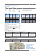
1.0 MODEL Specifications in blue are improved
MODEL
GEN 8-300 10-240 16-150 20-120 30-80 40-60 60-40 80-30 100-24 150-16 300-8 600-4
1.Rated output voltage(*1)
V 8 10 16 20 30 40 60 80 100 150 300 600
2.Rated Output Current(*2)
A 300 240 150 120 80 60 40 30 24 16 8 4
3.Rated Output Power
W 2400 2400 2400 2400 2400 2400 2400 2400 2400 2400 2400 2400
1.1 CONSTANT VOLTAGE MODE
1.Max.line regulation ( 0.01% of rated Vo+ 2mV )(*6) mV 2.8 3 3.5 4 5 6 8 10 12 17 32 62
2.Max load regulation ( 0.015% of rated Vo+5mV )(*7) mV 6.2 6.5 7.25 8 9.5 11 14 17 20 27. 5 50 95
3.Ripple and noise p-p 20MHz (*8)
mV
50 50 50 50 55 55
60
60 70
90 150
240
4.Ripple r.m.s 5Hz~1MHz
mV 6 6
6 6 6 6 6 7
10
20 45 60
5.Remote sense compensation/wire V 2 2 2 2 5 5 5 5 5 5 5 5
6.Temp. coefficient
PPM/°C
50PPM/°C of rated output
voltage
,following 30 minutes warm-up
7.Temp. stability 0.01% of rated Vout
over 8hrs interval following 30 minutes warm-up. Constant line, load & temp.
8.Warm-up drift Less than 0.05% of rated output voltage+2mV over 30 minutes following power On.
9.Up-prog. response time, 0~Vo Rated (*9) mS 15 20 30 40 40 60 80 100
10.Down-prog response
time
Full-load (*9) mS 10 10 20 20 20 20 30 50 50 80 100 100
No-load (*10)
mS 500 500 500 500 600 700 110 0 1200 1500 2500 3000 3000
11.Transient response time mS
Time for output voltage to recover within 0.5% of its rated output for a load change 10-90% of rated output current. Output
set-point: 10-100%, local sense. Less than 1mSec for models up to and including 100V. 2msec for models above 100V
1.2 CONSTANT CURRENT MODE
1.Max.line regulation (0.01% of rated Io+2mA)(*6) mA 32 26 17 14 10 8 6 5 4.4 3.6 2.8 2.4
2.Max.load regulation (0.02% of rated Io+5mA)(*11) mA 65 53 35 29 21 17 13 11 9.8 8.2 6.6 5.8
3.Ripple r.m.s 5Hz~1MHz . (*12)
mA
700 500 400 250 150 90 60 40 30 12 10 5
4.Load regulation thermal drift Less than 0.1% of rated output current over 30 minutes following load change.
5.Temp. coefficient
PPM/°C
70PPM/ºC from rated output current
, following 30 minutes warm-up.
6.Temp. stability 0.01% of rated Iout
over 8hrs. interval following 30minutes warm-up. Constant line, load & temperature.
7.Warm-up drift
8V~20V models: Less than ±0.5% of rated output current over 30 minutes following power On.
30V~600V models: Less than ±0.25% of rated output current over 30 minutes following power On.
1.3 PROTECTIVE FUNCTIONS
1. OCP 0~105% Constant Current
2. OCP Foldback Output shut down when power supply change from CV to CC. User selectable.
3. OVP type Inverter shut-down, manual reset by AC input recycle or by OUT button or by communication port command.
4. OVP trip point 0.5~10V 0.5~12V 1~18V 1~24V 2~36V 2~44V 5~66V 5~88V 5~110V 5~165V 5~330V 5~660V
5. Output Under Voltage Limit Preset by front panel or communication port. Prevents from adjusting Vout below limit.
6. Over Temp. Protection User selectable , latched or non-latched.
1.4 ANALOG PROGRAMMING AND MONITORING
1.Vout Voltage Programming 0~100%, 0~5V or 0~10V, user select. Accuracy and linearity:±0.5% of rated Vout.
2.Iout Voltage Programming (*13) 0~100%, 0~5V or 0~10V, user select. Accuracy and linearity:±1% of rated Iout.
3.Vout Resistor Programming 0~100%, 0~5/10Kohm full scale,user select.,Accuracy and linearity: ±1% of rated Vout.
4.Iout Resistor Programming (*13) 0~100%, 0~5/10Kohm full scale,user select. Accuracy and linearity:±1.5% of rated Iout.
5.On/Off control (rear panel) By electrical. Voltage: 0~0.6V/2~15V,or dry contact ,user selectable logic.
6.Output Current monitor (*13) 0~5V or 0~10V , Accuracy:±1% , user selectable.
7.Output Voltage monitor 0~5V or 0~10V ,Accuracy:±1% ,user selectable.
8.Power Supply OK signal TTL high (4~5V) -OK, 0V-Fail 500ohm series resistance.
9. CV/CC Indicator Open collector, CC mode: On, CV mode: Off, Maximum voltage: 30V, maximum sink current: 10mA
10. Enable/Disable Dry contact. Open:off , Short: on. Max. voltage at Enable/Disable in: 6V.
11. Local/Remote analog control By electrical signal or Open/Short: 0~0.6V or short: Remote, 2~15V or open: Local.
12. Local/Remote analog control Indicator Open collector, Local: Off, Remote: On. Maximum voltage: 30V, maximum sink current: 10mA.
1.5 FRONT PANEL
1.Control functions
Vout/ Iout manual adjust by separate encoders (coarse and fine adjustment selectable).
OVP/UVL manual adjust by Volt. Adjust encoder.
On/Off, Output on/off, Re-start modes (auto, safe), Foldback control (CV to CC), Go to local control.
Address selection by Voltage (or current) adjust encoder. Number of addresses:31.
Re-start modes (automatic restart, safe mode).
Baud rate selection: 1200,2400,4800,9600 and 19,200.
2.Display
Voltage: 4 digits ,
Accuracy: 0.05% of rated output Voltage ±1 count.
Current: 4 digits,
Accuracy: 0.2% of rated output current ±1 count.
3.Indications Voltage, Current, Alarm, Fine, Preview, Foldback, Local, Output On, Front Panel Lock, CVCC.
1.6 Interface Specifications for the GENESYS Series with RS-232/RS-485 Or Optional GPIB/LAN Interface Installed
1. Remote Voltage Programming (16 bit) V 8 10 15 20 30 40 60 80 100 150 300 600
Resolution (0.002% of Vo Rated)
mV
0.16 0.2 0.3 0.4 0.6 0.8 1.2 1.6 2 3 6 12
Accuracy (0.05% of Vo Rated) (*14)
mV
4 5 8 10 15 20 30 40 50 75 150 300
2. Remote Current Programming (16 bit)
Resolution (0.002% of Io Rated)
mA
6 4.80 3.00 2.40 1.60 1.20 0.80 0.60 0.48 0.32 0.16 0.08
Accuracy (0.2% of Io Rated+0.1% of Io Actual Output) (*13)
mA 900 720 450 360 240 180 120 90 72 48 24 12
3. Readback Voltage
Resolution (% of Vo Rated)
%
0.002 0. 011 0.007 0.006 0.004 0.003 0.002 0.002 0. 011 0.007 0.004 0.002
Resolution (Readback Voltage)
mV
0.16 1.10 1.05 1.20 1.20 1.20 1.20 1.60 11.0 0 10.50 12.00 12.00
Accuracy (0.05% of Vo Rated)
mV
4 5 8 10 15 20 30 40 50 75 150 300
4. Readback Current
Resolution (% of Io Rated )
%
0.004 0.005 0.007 0.009 0.002 0.002 0.003 0.004 0.005 0.007 0.002 0.003
Resolution (Readback Current )
mA
12 12 10.5 10.8 1.6 1.2 1.2 1.2 1.2 1.120 0.160 0.120
Accuracy (0.3% of Io Rated) (*13)
mA
900 720 450 360 240 180 120 90 72 48 24 12
5. OVP/UVL Programming
Resolution (0.1% of Vo Rated) mV 8 10 15 20 30 40 60 80 100 150 300 600
Accuracy (1% of Vo Rated) mV 80 100 150 200 300 400 600 800 1000 1500 3000 6000
4 | GENESYS™ | 2.4kW