
Data Sheet
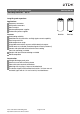
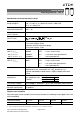
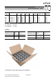
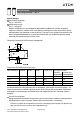
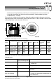
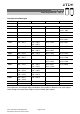

Table Of Contents

Minimal overall length tolerance (±0.35 mm) for mounting between heat sink and bus bar
Case with extra groove near the base for clamp mounting (recommended ring clamp
B44030A0165B ... A0190B)
This version is available only for capacitors without threaded stud and for diameters ≥ 64.3 mm.
Regarding ripple current and useful life, please refer to column I
AC,R
(B) in the table "Technical data
and ordering codes" and in the useful life curves.
Dimensions and weights for heat sink mounting:
Ter-
minal
Dimensions (mm) with insulating sleeve Min. reach
of screw
mm
Approx.
weight
g
d l ±1 l
1
±0.35 d
2
max. a +0.2/0.4
M5
M5
64.3 +0/0.8
64.3 +0/0.8
80.7
105.7
86.3
111.3
13.2
13.2
28.5
28.5
7.3
7.3
370
440
M6
M6
76.9 +0/0.7
76.9 +0/0.7
105.7
143.2
110.6
148.1
17.7
17.7
31.7
31.7
9.7
9.7
620
840
M6
M6
91.0 +0/2
91.0 +0/2
97.0
144.5
101.4
148.9
17.7
17.7
31.7
31.7
9.7
9.7
1000
1200
Dimensions for other sizes are available upon request.
Ordering codes:
Design Identification in third
block of ordering code
Remark
Low inductance (13 nH) M003 For capacitors with diameter d ≥ 64.3 mm and
V
R
≤ 450 V DC
For heat sink mounting M007 For capacitors with diameter d ≥ 64.3 mm and
without threaded stud
PAPR terminal style M050 For capacitors with V
R
≤ 450 V DC; not for low
inductance
PAPR terminal style and
heat sink mounting
M057 For capacitors with diameter d ≥ 64.3 mm,
V
R
≤ 450 V DC and without threaded stud; not
for low inductance
B43740, B43760
Extra long useful life 105 °C
Page 7 of 21Please read Cautions and warnings and
Important notes at the end of this document.