Inductors VHF chokes Series/Type: B82111B Date: March 2008 Data Sheet EPCOS AG 2008. Reproduction, publication and dissemination of this publication, enclosures hereto and the information contained therein without EPCOS’ prior express consent is prohibited.
VHF chokes B82111B Rated voltage 500 V AC/DC Rated current 2 A to 10 A Rated inductance 3 µH to 25 µH Construction ■ Ferrite cylinder core ■ Winding: single-layer, enamel copper wire, winding ends brought out as leads ■ Polyester insulating sleeve Features ■ ■ ■ ■ ■ High resonant frequency High rated current Suitable for wave soldering RoHS-compatible ENEC10 approval Applications ■ RF blocking and filtering ■ Interference suppression in small appliances Terminals ■ Central axial leads ■ Base material
VHF chokes B82111B Technical data and measuring conditions Test voltage Vtest 2500 V AC, 1 min Rated inductance LR Measured with LCR meter Agilent 4284A or impedance analyzer Agilent 4294A = 1 MHz Measuring frequency: LR ≤ 10 µH 10 µH < LR ≤ 1000 µH = 100 kHz Measuring voltage: 1V Measuring temperature: 20 °C Inductance tolerance ±20% Rated temperature TR 60 °C Rated current IR Maximum permissible DC current at rated temperature DC resistance Rtyp Measured at 20 °C, tolerance ±20%, typical valu
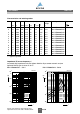
VHF chokes B82111B Characteristics and ordering codes LR Rtyp fres µH Ω MHz l1–1.5 l2–3 d1 max. d2 2 17 0.063 100 18.3 24 7.0 0.45 3.0 3 3 3 3 4 4 4 6 6 6 9 10 8 13 20 25 6 11 15 4 6 9 3 5 0.025 0.024 0.054 0.046 0.017 0.020 0.024 0.014 0.010 0.012 0.006 0.005 145 170 125 85 170 150 120 205 200 150 220 175 18.3 24.5 24.5 28.5 18.3 24.5 28.5 18.3 24.5 28.5 24.5 28.5 24 29 29 34 24 29 34 24 29 34 29 34 7.0 6.5 6.0 8.5 7.5 6.5 8.5 7.5 7.0 9.0 7.5 9.5 0.63 0.67 0.5 0.63 0.75 0.71 0.
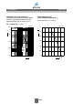
VHF chokes B82111B Impedance |Z| versus frequency f measured with impedance analyzer Agilent 4294A or S-parameter network analyzer Agilent 8753ES, typical values at 20 °C Current derating Iop/IR versus ambient temperature TA (rated temperature TR = 60 °C) B82111B0000C021…C024 IND0156-R 10 6 Ω IND0143-T-E 1.2 B82111B I op IR |Z| 1.0 10 5 0.8 10 4 0.6 0.4 10 3 10 2 7 10 C024 C023 C022 C021 10 8 0.
Cautions and warnings ■ Please note the recommendations in our Inductors data book (latest edition) and in the data sheets. – Particular attention should be paid to the derating curves given there. – The soldering conditions should also be observed. Temperatures quoted in relation to wave soldering refer to the pin, not the housing.
Important notes The following applies to all products named in this publication: 1. Some parts of this publication contain statements about the suitability of our products for certain areas of application. These statements are based on our knowledge of typical requirements that are often placed on our products in the areas of application concerned.