
User's Manual


5
ENGLISH
E
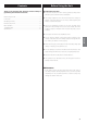
Speaker Connections
Caution:
To avoid damaging the speakers with a sudden high-level
signal, be sure to switch the power off before connecting the
speakers.
<
Check the impedance of your speakers. Connect speaker with
an impedance of 4 to 16 ohms when using only one pair of
speakers (SPEAKERS A or SPEAKERS B). When using two pairs
of speakers simultaneously, the impedance should be 8 to 16
ohms.
<
The black speaker terminals are _ (negative).
Generally, the + side of the speaker cable is marked to make
it distinguishable from the _ side of the cable. Connect this
marked side to the + terminal and the unmarked side to the
black _ terminal.
Caution:
The metal portions of the two separate wires should not touch
or an electrical short can occur. Shorted wires can create a fire
hazard or induce a failure in your equipment.
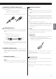
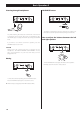
How to connect
Speakers A, B
1. Turn the terminal cap counterclockwise to loosen it. The speaker
terminal caps cannot be fully removed from the base.
2. Insert the wire into the terminal fully and turn the terminal cap
clockwise to securely connect it .
<
Make sure none of the wire insulation is under the terminal, only
the bare, stripped wire.
<
Make sure the wire is fastened firmly by pulling the cable lightly.
F
AC power cord
After all other connections are complete, connect the power cord
to the AC wall socket.
< Be sure to connect the power cord to an AC outlet which supplies
the correct voltage.
< Hold the power plug when plugging in or unplugging the
power cord.
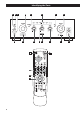
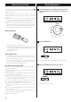
A
PHONO jacks/SIGNAL GND terminal
Connect the turntable’s RCA pin cords to PHONO jacks. Make
sure to connect:
white plug q white jack (L: left channel)
red plug q red jack (R: right channel)
Connect the turntable’s ground cord to SIGNAL GND terminal.
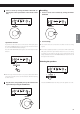
B
AUDIO IN/OUT jacks
Analog 2-channel audio signal is input or output from these
jacks. Connect the component with commercially-available RCA
cables.
Make sure to connect:
white plug
q
white jack (L: left channel)
red plug
q
red jack (R: right channel)
White (L)
Red (R)
White (L)
Red (R)
< Be sure to insert each plug securely. To prevent hum and noise,
avoid bundling the signal connection cables together with the
AC power cord or speaker cables.
C
REMOTE CONTROL jacks
If you have TEAC T-R650, TR-650DAB or CD-P650, connect the
REMOTE CONTROL jack (A or B) of each component by the
remote control cord (provided with the T-R650, T-R650DAB or
CD-P650).
D
AC Outlet (switched)
This outlet is active only when the unit is on.
Caution:
Make sure that the total power consumption of all equipment
connected to the outlet does not exceed 500mA or 100 watts.