MODEL RTA-8211 ASSEMBLY INSTRUCTIONS Thank you for purchasing our product. Scan QR Code to view Full assembly video REV.
RTA-8211 P.1 • Please read carefully the assembly instructions before the installation. • Do not discard this manual or any of the packaging material until the unit has been completely assembled. • Scan QR Code to view full assembly and step video. • Might require two people. P.
RTA-8211 P.2 P.
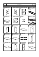
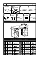
RTA-8211 P.3 21 x1 22 Sliders for keyboard 23 Top panel for CPU cabinet x1 panel set (Silver with threaded P.
RTA-8211 P.4 P.4 ☛ This unit uses cam bolts and locks. The following explains how to use them. This is not an assembly step; it is a guide for when you are actually doing the assembly using this kind of hardware. Cam Bolt Cam Lock 1. Screw the bolt into the corresponding panel. 2. Place the other panel over the panel with the bolt, then insert the cam lock to join the bolt’s head. If the cam lock does not want to enter, check its proper alignment.
P.5 RTA-8211 P.5 BEFORE YOU START THE ASSEMBLY, PLEASE READ THE FOLLOWING TIPS AND WARNINGS. ❶ Do a quick inventory to make sure the package contains all the parts and hardware listed in the assembly instructions. ❼ To avoid misalignments, always leave the screws loose and tighten them until all pieces are positioned correctly. ❷ Missing, damaged and defective parts can be replaced at no cost to you. Please refer to the last pages on this manual.
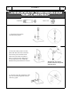
RTA-8211 P.6 P.6 ASSEMBLY STEPS STEP 1 Hardware: L M6x25 4 Pcs • Attach the bolts L to the drawer front panel 3. • Make sure the cam locks on panels 1 and 2 are aligned to receive the bolts, and attach the panels to panel 3. • Turn the cam locks to lock the pieces. Please remember this procedure, which is also explained in page 4.
RTA-8211 P.7 STEP 3 • Grab all the 8 pieces of sliders 8 and set aside the 4 “Flat” pieces as they will be used until next step. • Flip the drawer and attach the “L” shaped sliders with screws B, making sure the wheel goes towards the back, and that the sliders don’t protrude, otherwise, the drawers raise 1” and won’t fit in the unit. • Repeat steps 1 through 3 for the second drawer. Hardware: B ST3x15 P.7 4 Pcs Scan QR Code to view this step r (F CORRECT: Sliders don’t protrude on the bottom.
RTA-8211 P.8 STEP 5 Hardware: B ST3x15 6 Pcs P.8 Important: Make sure you use in this step the correct sliders 4 which are black, longer, and have more holes than sliders 22. • Attach the sliders 4 to the top sets of holes on panels 9 and 10 with screws B, starting with the front holes first by opening the sliders slowly until you see the first hole through the big opening; then open the sliders completely and attach on the 2 back holes.
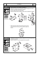
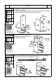
RTA-8211 P.9 STEP 8 Hardware: L ST5x40 M6x25 4 Pcs • Assemble the back panel 12 to the bottom panel 13 with bolts L as explained in page 4. • Then secure the panel 12 to the side panels 9 and 10 with screws K. • Finally attach the grommet N to the back panel 12. (Top) 2 Pcs N 1 pc K (Fro (F ron nt) N Scan QR Code to view this step Hardware: 4 Pc M6x40 12 10 10 12 Cam lock alignment L 13 STEP 9 A (Top) (Fro (F ron nt) K P.
RTA-8211 P.10 STEP 11 Hardware: A M6x40 4 Pcs P.10 Assemble the left panel 16 and the right panel 18 to the bottom panel 20 with bolts A as explained in page 4.
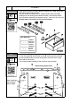
RTA-8211 P.11 STEP 14 Assemble the back panel 27 to the left panel 12 and the right panel 19 with bolts L as explained in page 4. Hardware: L M6x25 P.11 4 Pcs 19 27 12 Cam locks alignment Scan QR Code to view this step STEP 15 Assemble the slider bases 25 to the center holes on the tabletop 24 with screws F. Make sure the bases face towards the inside.
RTA-8211 P.12 STEP 17 Assemble the support tubes 26 to the tabletop 24 with screws E. Hardware: E ST4x14 P.12 8 Pcs 26 26 24 Scan QR Code to view this step STEP 18 Hardware: H M6x35 2 Pcs I L 4 Pcs M6x25 (Front) • Place the plastic washers I over the center of the holes on panels 14 and 21. • Attach the bolts L to the back holes of the tabletop 24. • With the help of another person, carefully place the tabletop 24 over the structure so the bolts enter into the back panels 12 and 19.
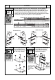
RTA-8211 P.13 STEP 19 Hardware: E ST4x14 4 Pcs P.13 Slide out the sliders 22 and place the keyboard panel 23 over the tabs making the pre-drilled holes match, then secure the panel with screws E from underneath. 23 22 23 Scan QR Code to view this step STEP 20 Insert the long end of the screws J into one end of the tubes 28, then attach the tubes with the short end of the screws into panel 29.
RTA-8211 P.14 STEP 22 Hardware: M 4 Pcs P.14 • Insert the drawers into the left cabinet starting with the bottom one, then the top drawer. The top drawer might need to be inserted at an angle with its front facing down. • Insert the pins M into one of the 3 sets of holes on the side panels 16 and 18 on the CPU cabinet, and install the adjustable panel 17. Scan QR Code to view this step 17 (Front) 16 ALL DONE! 18 Give yourself a nice pat on the back.
RTA-8211 P.15 P.15 AFTER THE ASSEMBLY IS DONE, PLEASE READ CAREFULLY THE FOLLOWING CARE AND MAINTENANCE WARNINGS: WEIGHT LIMITS 30 Lbs. (13.6 Kg) 80 Lbs. (36.3 Kg) 22 Lbs. (10 Kg) 30 Lbs. 30 Lbs. (13.6 Kg) (13.6 Kg) • Do not exceed the indicated weight limits. • Do not expose the surfaces to direct sunlight or to extreme environmental conditions. • Clean the surfaces preferable with a clean cloth damped in a solution of mild soap and water, then dry with a clean towel.
P.16 RTA-8211 P.16 TECHNI MOBILI WARRANTY DESKS/LAPTOP CARTS/FILE CABINETS: LIMITED 5-YEAR WARRANTY TV Stand/Entertainment Center: 2 YEAR WARRANTY RTA Products, LLC warrants to the Original Purchaser who acquired a new product from RTA Products or its authorized resellers that this product will be free from defects in its workmanship and materials, under normal use and service conditions, as described herein.
P.17 RTA-8211 P.17 FOR SEVERAL HELP OPTIONS INCLUDING REPLACEMENT PARTS ORDERS _________________________________________________________________ VISIT: WWW.TECHNIMOBILI.COM CLICK ON SUPPORT TAB Scan QR Code to order replacement parts OR EMAIL US: SUPPORT@RTAPRODUCTS.