Geavanceerde gebruikershandleiding internet Technicolor TC7210
Welkom bij Internet van Ziggo Van harte welkom bij Internet van Ziggo. Met deze geavanceerde handleiding kunt u de instellingen wijzigen van uw Wi-Fi modem. Let op! Het aanpassen van de geavanceerde instellingen is op eigen risico. Ziggo heeft uw Wi-Fi modem standaard zo ingesteld dat het Wi-Fi modem goed werkt bij normaal gebruik. Mocht het Wi-Fi modem niet goed werken nadat u de geavanceerde instellingen gewijzigd heeft, dan adviseren wij u de standaardinstellingen te herstellen.
Inhoudsopgave 1. Internet van Ziggo 5 1.1 Symbolen 5 2. Inloggen op de gebruikersomgeving 6 2.1 Geavanceerde instellingen 6 3. Connections and setup 9 3.1 Wireless Voice Gateway Overview 3.2 Relationship amoung the devices 3.3 Connecting the Wireless Voice Gateway to a Single Computer 14 4. Web configuration 19 4.1 Accessing the Web Configuration 4.2 Gateway – Status Web Page Group 4.3 Gateway – Network Web Page Group 4.4 Gateway – Advanced Web Page Group 4.5 Gateway – Firewall Web Page Group 4.
1. Internet van Ziggo Deze handleiding leidt u stap voor stap door de geavanceerde instellingen van Internet van Ziggo. Wij adviseren u om deze handleiding op uw computer op te slaan in verband met het eventueel wegvallen van de internetverbinding. Heeft u hulp nodig? Stel uw vraag aan onze Online Assistent op www.ziggo.nl/klantenservice of bekijk het portal op www.ziggo.nl/WiFimodem. De afbeeldingen in deze handleiding kunnen afwijken van de werkelijkheid. 1.
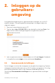
2. Inloggen op de gebruikersomgeving In de gebruikersomgeving kunt u geavanceerde instellingen van uw Wi-Fi modem wijzigen. Om op de gebruikersomgeving in te loggen volgt u de volgende stappen: 1. Open een internet browser op uw PC. 2. Typ het adres http://192.168.178.1 in de adresbalk en druk op Enter. Het login venster waarin wordt gevraagd om een gebruikersnaam en wachtwoord verschijnt. 3. Voer uw gebruikersnaam en wachtwoord in en klik op Inloggen.
Handleiding Internet van Ziggo 7
Handleiding Internet van Ziggo 8
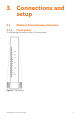
3. Connections and setup 3.1 Wireless Voice Gateway Overview 3.1.
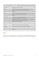
LED Description POWER Indicates the Power status. DS Indicates the status of Data reception by the cable modem from the Network (Downstream Traffic). US Indicates the status of Data transmission by the cable modem to the Network (Upstream Traffic). ONLINE Displays the status of your cable connection. The light is off when no cable connection is detected and fully lit when the modem has established a connection with the network and data can be transferred.
TC7210 Power Internet DS US Online 1 2 3 4 Boot-up Operation ON ON ON ON ON ON ON ON 0.25 SECOND ON FLASH FLASH FLASH X X X X X ON ON LAN ON ON USB Wireless TEL 1 TEL 2 Description ON X ON ON Power on .
LED Status when WPS State is In-progress Green LED will blink with 2 sec On -1 sec OFF cycle Success Green LED will remain ON for 300 secs before turning OFF Error”/ “Timeout Red LED will blink with 250 msec ON- 250 msec OFF cycle indefinitely Session overlap Red LED will turn ON-OFF with 250 msec duration for 2 seconds followed by turning OFF for 500 msec. This cycle will repeat for a total duration of 120 seconds. table 1: LED behaviour 3.1.
Connector Description Power switch Power on, off the Cable modem. Power jack Connector for DC12V. Cable Connector for the cable network. Reset To restart the modem or press over 5 seconds can default the modem. USB Host USB 2.0 connector LAN 4 Gige Ethernet ports, RJ-45 connector. TEL 1-2 2 Phone RJ11 Connectors. table 2: Rear panel description 3.1.3 Side panel for WPS figure 3: Side panel WPS – Indicates the status of the WPS functionality. WPS button: Wi-Fi Protected SetupTM.
3.2 Relationship amoung the devices This illustration shows a cable company that offers DOCSIS/Euro-DOCSIS and PacketCable/Euro-PacketCable compliant voice/data services. figure 4: Connection overview 3.2.1 What the Modem does The Wireless Voice Gateway provides high-speed Internet access as well as cost-effective, toll-quality telephone voice and fax/modem services over residential, commercial, and education subscribers on public and private networks via an existing CATV infrastructure.
Check with your cable company to make sure you have everything you need to begin; they’ll know if you need to install special software or re-configure your computer to make your cable internet service work for you. 3.2.3 Contact your local cable company You will need to contact your cable company to establish an Internet account before you can use your gateway.
3.3 Connecting the Wireless Voice Gateway to a Single Computer This section of the manual explains how to connect your Wireless Voice Gateway to the Ethernet port on your computer and install the necessary software. Please refer to Figure 1-5 to help you connect your Digital Cable Modem for the best possible connection. 3.3.1 1. Attaching the Cable TV Wire to the Wireless Voice Gateway Locate the Cable TV wire. You may find it one of three ways: a.
3.3.2 Installation procedure for connecting to the Ethernet interface Follow these steps for proper installation. Plug the coaxial cable to the cable wall outlet and the other end to the modem’s cable connector. Let op! To ensure a fast registration of the modem, the coaxial cable must be connected to the modem before it is powered on. Plug the power supply into the socket of the cable modem and two-pin plug in the AC outlet then press the Power Switch, power on the modem.
3.3.3 Telephone or Fax Connection When properly connected, most telephony devices can be used with the Wireless Voice Gateway just as with a conventional telephone service. To make a normal telephone call, pick up the handset; listen for a dial tone, then dial the desired number. For services such as call waiting, use the hook switch (or FLASH button) to change calls. The following procedures describe some of the possible connection schemes for using telephony devices with the Wireless Voice Gateway. 1.
4. Web configuration To make sure that you can access the Internet successfully, please check the following first. 1. Make sure the connection (through Ethernet) between the Wireless Voice Gateway and your computer is OK. 2. Make sure the TCP/IP protocol is set properly. 3. Subscribe to a Cable Company. 4.1 Accessing the Web Configuration The Wireless Voice Gateway offers local management capability through a built-in HTTP server and a number of diagnostic and configuration web pages.
4.1.1 Outline of Web Manager The main screen will be shown as below. figure 8: Outline of Web Manager Main Menu The hyperlinks on the top of the page, including Gateway, VoIP and several sub-menu items Sub Menu Under the main menu, sub menu use to enter each function, e.g., Status, Network, Firewall… Title The sidebar on the left side of the page indicates the title of this management interface, e.g.
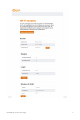
4.1.2 Warning message to change the password At your first connection or while the password is the default one, a warning message is displayed on the top banner of each Web configuration page. We want to encourage you to change the password in order to enforce the security of your modem. Please refer to the chapter password page 25 for more information. figure 9: Gateway\Status\Password To change the password: type the password, and re-enter it again.
If the password is accepted, you are required to re log on the web pages: figure 10: Password request dialog 4.2 Gateway – Status Web Page Group 4.2.1 Software The information section shows the hardware and software information about your gateway. The status section of this page shows how long your gateway has operated since last time being powered up, and some key information the Cable Modem received during the initialization process with your cable company.
to have Internet connectivity. If not, you may not have Internet access, and should contact your cable company to resolve this.
4.2.2 Connection This page reports current connection status containing startup procedures, downstream and upstream status, CM online information, and so on. The information can be useful to your cable company’s support technician if you’re having problems.
4.2.3 Password By default, the username is ziggo and the password is draadloos. This is set by different actions (non exhaustive list): • at the manufactory level, • following a reset factory on the modem, • following a reset from the operator, • following a change by the user who wants to come back to the default setting after using its own settings When the current password is the default one, the user is strongly encouraged to change the default web password.
Let op! We are always suggesting you to modify the password. This is a basic protection against wrongful access to the Gateway Web pages. figure 13: Gateway\Status\Password To change the password: type the password, and re-enter it again.
If the password is not accepted, an error message is displayed: Please reflash the web and wait for Password dialog pop-up, then typing the correct username and password again. 4.2.4 Diagnostics This page offers basic diagnostic tools for you to use when connectivity problems occur. When you ping an Internet device, you send a packet to its TCP/IP stack, and it sends one back to yours.
4.2.5 Event Log This page displays the contents of the SNMP event log. Press Clear Log button to clear the logs.
4.2.6 Initial Scan To speed up the modem’s first time connection, enter known downstream frequency and/or upstream channel ID information here. Then click Apply and Reboot button to start scanning the cable network beginning with the values supplied here. The value is provided in Hertz.
4.2.7 Backup/Restore This page allows you to save your current settings locally on your PC, or restore settings previously saved. The default file name is GatewaySettings.bin. figure 18: Gateway\Status\ Backup/Restore 4.3 Gateway – Network Web Page Group 4.3.1 LAN You can activate the DHCP server function for the LAN on this page.
DHCP Server: • Select the check point of Yes or No to enable or disable a simple DHCP server for LAN. • Configure the IP address numbers for the DHCP server with Lease pool start and Lease pool end. • Configure the IP address lease time with Lease time for DHCP server. Default value is 604800 seconds.
4.3.2 WAN You can configure the optional internal DHCP server for the WAN on this page. This can be required by some ISP providers. Select different WAN Connection Type will lead to different contents. Take the WAN connection type-DHCP for example, you can release and renew the WAN lease by pressing the buttons. You can enter a spoofed MAC address that causes your gateway networking stack to use that MAC address when communicating instead of the usual WAN MAC address, e.g.
4.3.3 Computers This page displays the status of the DHCP clients and current system time. You can cancel an IP address lease by selecting it in the DHCP Client Lease Info list and then clicking the Force Available button. If you do so, you may have to perform a DHCP Renew on that PC, so that it can obtain a new lease.
4.3.4 DDNS - Dynamic DNS service This page allows to setup for Dynamic DNS server. figure 22: Gateway\Network\DDNS DDNS Service Choose Enabled (www.DynDNS.org) to enable the basic setting. Choose Disabled to close the basic setting. Username The username that you registered with your DDNS provider. Password The password that you registered with your DDNS provider. Host Name The domain name or host name that is registered with your DDNS provider.
4.3.5 Time This page allows configuration and display of the system time obtained from network servers via Simple Network Time Protocol. The system has to be reset for any changes to take effect.
4.3.6 FTP Diagnostics This page allows to test download and upload transmit rate through FTP. Choose known FTP server and Filename with correct username and password then choose direction to Download or Upload. Press the Start button to start. figure 24: Gateway\Network\FTP Diagnostics You will see the result on the page, when transmit done.
4.3.7 Port-base Passthrough This page allows the configuration of each Ethernet Port. Per default, each Ethernet port is routed. If you enable the Passthrough, the Ethernet Port will have a direct connection to the Network. Note that access to this web access can be denied by your Cable operator.
4.4 Gateway – Advanced Web Page Group 4.4.1 Options This page allows you to enable/disable some features of the Wireless Voice Gateway. figure 27: Gateway\Advanced\Options WAN Blocking Prevents others on the WAN side from being able to ping your gateway. With WAN Blocking enabled, your gateway will not respond to pings it receives, effectively “hiding” your gateway. PPTP PassThrough Enables PPTP type packets to pass between WAN and LAN.
Remote Config Management Mmakes the configuration web pages in your gateway accessible from the WAN side. Note that page access is limited to only those who know the gateway access password. When accessing your gateway from a remote location, your must use HTTP port 8080 and the WAN IP address of the gateway. e.g., if the WAN IP address is 157.254.5.7, you would navigate to http://157.254.5.7:8080 to reach your gateway. Multicast Enable Enables multicast traffic to pass between WAN and LAN.
4.4.2 IP Filtering This page enables you to enter the IP address ranges of PCs on your LAN that you don’t want to have outbound access to the WAN. These PCs can still communicate with each other on your LAN, but packets they send to WAN addresses are blocked by the gateway.
4.4.3 MAC Filtering This page enables you to enter the MAC address of specific PCs on your LAN that you do not wish to have outbound access to the WAN. As with IP filtering, these PCs can still communicate with each other through the gateway, but packets they send to WAN addresses are blocked.
4.4.4 Port Filtering This page allows you to enter ranges of destination ports (applications) that you don’t want your LAN PCs to send packets to. Any packets your LAN PCs send to these destination ports will be blocked. For example, you could block access to worldwide web browsing (http = port 80) but still allow email service (SMTP port 25 and POP-3 port 110). To enable port filtering, set Start Port and End Port for each range, and click Apply.
For example: To block HTTP (port 80) browse and restrict mail send from POP3(port 110), setting as following: figure 31: Gateway\Advanced\Port Filtering Setting port value, block protocol (Both for TCP & UDP), check Enable then Apply.
4.4.5 Forwarding For LAN to WAN communications, the gateway normally only allows you to originate an IP connection with a PC on the WAN; it will ignore attempts of the WAN PC to originate a connection onto your PC. This protects you from malicious attacks from outsiders. However, sometimes you may wish for anyone outside to be able to originate a connection to a particular PC on your LAN if the destination port (application) matches one you specify.
Press Create IPv4 button you will see follow options shows on the page. To specify rules, choose Service Name or Port number range to set up. IP Address 0.0.0.0 means allow all IP address. figure 33: Gateway\Advanced\Forwarding setting This page allows you to specify up to rules. For example, to specify that outsiders should have access to an FTP server you have running at 192.168.0.
This page allows you to specify up to rules. For example, to specify that outsiders should have access to an FTP server you have running at 192.168.0.5, create a rule with that address and Start Port =20 and End Port =21 (FTP port ranges) and Protocol = TCP (FTP runs over TCP and the other transport protocol, UDP), and click Apply. This will cause inbound packets that match to be forwarded to that PC rather than blocked.
Press Create button to specify rules. figure 36: Gateway\Advanced\Port Triggers Port Triggering works as follows. Imagine you want to play a particular game with PCs somewhere on the Internet.
4.4.7 DMZ Host Use this page to designate one PC on your LAN that should be left accessible to all PCs from the WAN side, for all ports. e.g., if you put an HTTP server on this machine, anyone will be able to access that HTTP server by using your gateway IP address as the destination. A setting of “0” indicates NO DMZ PC. Host is another Internet term for a PC connected to the Internet.
4.4.8 RIP (Routing Information Protocol) Setup This feature enables the gateway to be used in small business situations where more than one LAN (local area network) is installed. The RIP protocol provides the gateway a means to “advertise” available IP routes to these LANs to your cable operator, so packets can be routed properly in this situation. Your cable operator will advise you during installation if any setting changes are required here. figure 38: Gateway\Advanced\RIP Setup 4.
If you want the gateway to exclude your selected filters to certain computers on your LAN, enter their MAC addresses in the Trusted Computers area of this page.
4.5.2 TOD Filtering Use this page to set rules that will block specific LAN side PCs from accessing the Internet, but only at specific days and times. Specify a PC by its hardware MAC address, and then use the tools to specify blocking time. Finally, click the Apply button to save your settings.
4.5.3 Local Log The gateway builds a log of firewall blocking actions that the firewall has taken. Using the Local Log page lets you specify an email address to which you want the gateway to email this log. You must also tell the gateway your outgoing (i.e. SMTP) email server’s name, so it can direct the email to it. Enable Email Alerts has the gateway forward email notices when Firewall protection events occur. Click E-mail Log to immediately send the email log.
4.5.4 Remote Log The Remote Log page allows you to specify the IP address where a SysLog server is located on the LAN Side and select different types of firewall events that may occur. Then, each time such an event occurs, notification is automatically sent to this log server. figure 42: Gateway\Firewall\Remote Log 4.6 Gateway – Parental Control Web Page Group 4.6.
figure 43: Gateway\Parental Control\Basic 4.7 Gateway – Wireless Web Page Group The Wireless web pages group enables a variety of settings that can provide secure and reliable wireless communications for even the most demanding tech-savvy user. The Wireless Voice Gateway offers a choice of 802.
such as cordless phones. If your wireless PC is experiencing very sluggish or dramatically slower communication compared with the speed you achieve on your PC that is wired to the gateway, try changing the channel number. See the 802.11b/g/n Basic Web Page discussion below for details. Authentication Authentication enables you to restrict your gateway from communicating with any remote wireless PCs that aren’t yours. The following minimum authentication-related changes to factory defaults are recommended.
4.7.1 Radio To set the basic configuration for the wireless features, click RADIO from the Wireless menu. These must match the settings you make on your wirelessequipped PC on the LAN side. figure 44: Gateway/Wireless/Radio Interface The wireless radio in your gateway can be completely de-activated by changing Interface to Disabled. Click the Apply button to save your settings.
802.11 n-mode It may help you to Enable or Disable the 11N mode. To enable you need to select Auto, to disable you need to select Off, and so force the AP to operate in 802.11 n-mode. Bandwidth Select wireless channel width 20 MHz is for default value (bandwidth taken by wireless signals of this access point.) Sideband for Control Channel (40 MHz only) There is “Lower” and “Upper” can be selected if Bandwidth 40 MHz was Enabled. Control Channel In 802.11 Band 2.4GHz, there are 1 to 13 channels.
Setting Description Value List or Range Default Network Name Set the Network Name (also (SSID) known as SSID) of this network. Up to 32character string containing ASCII characters only PExxx Network Type Select Closed to hide the network from active scans. Select Open to reveal the network to active scans. Open, Closed Open New Channel Select a particular channel on 1-13 which to operate. 1 or 6 or 11 Interface Enable or disable the wireless Enabled, Disabled Enabled interface.
4.7.2 Primary Network This page allows you to configure the Network Authentication. It provides several different modes of wireless security. You will have to enter proper information according to the mode you select.
802.11x Authentication introduction If you enable the 802.11x authentication function, you will have to offer the following information. WPA/WPA2 (Wi-fi Protected Access) It must be used in conjunction with an authentication server such as RADIUS to provide centralized access control and management. It can provide stronger encryption and authentication solution than none WPA modes. WPA2 is the second generation of WPA security.
WPA/WPA2 For the WPA/WPA2 network Authentication, the settings that you can adjust including WPA/WPA2 Encryption, RADIUS Server, RADIUS Port, RADIUS Key, Group Key Rotation Interval, and WPA/WPA2 Re-auth Interval. WPA/WPA2 Encryption There are two types that you can choose, AES, TKIP+AES. TKIP takes the original master key only as a starting point and derives its encryption keys mathematically from this mater key.
figure 46: WPA/WPA2 WPA-PSK/ WPA2-PSK For the WPA-PSK/WPA2-PSK network Authentication, the settings that you can adjust including WPA/WPA2 Encryption, WPA Pre-Shared Key, and Group key Rotation Interval. WPA Pre-Shared Key Please type the key to be between 8 and 63 characters, or 64 hexadecimal digits. Only the devices with a matching key that you set here can join this network.
WEP Encryption You can choose 64-bit or 128-bit according to your needs. If you choose Disabled, the Network Keys will not be shown on this page. If selected, the data is encrypted using the key before being transmitted. e.g., If you set 128-bit in this field, then the receiving station must be set to use the 128 Bit Encryption, and have the same Key value too. Otherwise, it will not be able to decrypt the data.
figure 48: WEP (64-bit) / WEP (128-bit) Automatic Security Configuration Wi-Fi Protected SetupTM (WPS) is an easy and secure way of configuring and connecting your Wireless access point. In this case, the Wireless Voice Gateway is the Access Point (AP), and Your PC (or Wireless Device) is called the STA. When configuring your Wireless Network via WPS, Messages are exchanged between the STA and AP in order to configure the Security Settings on both devices.
figure 49: Automatic Security Configuration If you type in Client PIN, then the WPS Add Client option will appear as shown below. figure 50: WPS/Push-Button And then if you click “Add” button then WPS Add Client page will appear as shown in Fig. 38.
And WPS Configure Status will be “In progress”, after establishing the connection the WPS Configure Status will be “Success!” as shown below. After succesful connection the client will get IP adress from AP and then internet will be accessible. figure 52: WPS Setup AP successful/PUSH WPS Add Client process also can finish with type in Authorized Client MAC. 4.7.3 Access Control This page allows you to control device that can connect to the AP and list all connected clients.
MAC Restrict Mode Click Disabled to welcome all of the clients on the network; select Allow to permit only the clients on the list to access the cable modem; or choose Deny to prevent the clients on the list to access this device. MAC Address Your Gateway identifies wireless PCs by their Wireless MAC Address. This address consists of a string of 6 pairs of numbers 0-9 and letters A-F, such as 00 90 4B F0 FF 50. It is usually printed on the Wireless card of the device (e.g. the PCMCIA card in a laptop).
4.7.4 Advanced This page allows you to configure some advanced settings. The factory default values should provide good results in most cases. We don’t recommend you change these settings unless you have technical knowledge of 802.11 wireless technology. For expert users, details of all settings on this web page are provided below.
Basis Rate Set The rates that for all clients want to associate with. Choose “Default” and “All” for the 802.11a/b/g/n/ac. Multicast Rate The baseline levels that wireless device able to deliver in order to connect to the wireless voice gateway. Lower multicast rates mean weaker, farther signals are allowed to connection. Higher multicast rates mean that only close, strong signals are allowed. NPHY Rate Set the Physical Layer rate. The rate always set “Use Legacy Rate”.
4.7.5 Bridging The Bridging page provides a location where settings can be adjusted related to the WDS (Wireless Distribution System) feature. WDS is a system that enables the interconnection of access points wirelessly. It may also be referred to as repeater mode because it appears to bridge and accept wireless clients at the same time (unlike traditional bridging).
4.7.6 802.11 Wi-fi Multimedia Wi-Fi Multimedia (WMM) is a component of the IEEE 802.11e wireless LAN standard for quality of service (QoS). The QoS assigns priority to the selected network traffic and prevents packet collisions and delays thus improving VoIP calls and watching video over WLANs. figure 56: Gateway\Wireless\WMM Enable WWM This field allows you to enable WMM to improve multimedia transmission. Enable WWM NoAcknowledgment This field allows you to enable WMM NoAcknowledgement.
EDCA AP parameters proposal : specifies the transmit parameter for traffic transmitted from the AP to the STA for the 4 Access Categories: Best effort (AC_BE), Background (AC_BK) Video (AC_VI) and voice (AC_VO). Transmit parameters include contention window (CWmin CWmax), arbitration Inter Frame Spacing Number AIFSN, and Transmit opportunity Limit (TXOP limit ). Admission Control specifies if admission control is enforced for the Access categories.
4.8 Gateway – USB Web Page Group 4.8.1 Media Server This page controls configuration and scanning of the Gateway's media server. Choose Scan all Files will scan your approved USB devices for sharing files. Scan Files by Type for specific file type or all of types for sharing. Choose file types form Available File Types to Selected File Types.
4.8.2 USB Basic settings This page allows basic control of the USB devices shared over the network. Enable USB This field controls which USB device (Key or Hard Disk) can be connected to the Gateway. All will authorize all USB Devices connected to devices. Approved will authorize devices that have been the USB port: previously approved on this gateway. None will block any USB Device on the Gateway. To approve devices (PC), click on the button Approved Devices.
4.8.3 Approved Devices settings This page allows the configuration of the USB storage device(s) shared over the network. Add Available USB Devices as Approved USB Devices then apply changes. If you want to remove USB devices, propose you press Safely Remove Device button first.
4.8.4 Storage Basic This page shows the status of the USB folders shared over the network. Basic option defines shared files in all approved devices and specified folders or only specified folders. You can edit Shared Network Folders and observe the detail of folders.
4.8.5 Storage Advanced This page shows the status of the folders shared over the network. Advanced option provides FTP option to share files as a FTP server.
4.9 VoIP – Basic Web Page Group 4.9.1 Basic LAN This page displays the basic LAN status of this device, including the downstream and upstream status, device information, and interface parameters. You can select specific interface from the Interface Name drop-down menu.
4.9.2 Hardware Info The hardware Info is displayed on this page.
4.9.3 Event Log The Docsis and PacketCable event logs are displayed on this web page.
figure 65: VoIP\Basic\Event log\PacketCable 4.9.4 CM State This page shows the current state of the cable modem.
5. Networking 5.1 Communications Data communication involves the flow of packets of data from one device to another. These devices include personal computers, Ethernet, cable modems, digital routers and switches, and highly integrated devices that combine functions, like the Wireless Cable Gateway. The gateway integrates the functionality often found in two separate devices into one.
3. Communication between your PCs and the networking side. Example: The Wireless Cable Gateway offers a number of built-in web pages which you can use to configure its networking side; when you communicate with the networking side, your communication is following this path. Each packet on the Internet addressed to a PC in your home travels from the Internet down- stream on the cable company’s system to the WAN side of your Wireless Cable Gateway.
the Internet, the stack must also be assigned an IP (Internet Protocol) address. 192.168.100.1 is an example of an IP address. A TCP/IP stack can be configured to get this IP address by various means, including a DHCP server, by you directly entering it, or sometimes by a PC generating one of its own. Ethernet requires that each TCP/IP stack on the Wireless Cable Gateway also have associated with it an Ethernet MAC (Media Access Control) address.
5.6 Cable Modem (CM) Mode figure 68: Cable Modem Mode figure 69: Two IP stacks are activated in cable modem mode CM (Cable Modem) Mode provides basic home networking. In this mode, two IP stacks are active: • IP Stack 1 - for use by the cable company to communicate with the cable modem section only. This stack receives its IP address from the cable company during CM initialization. It uses the MAC address printed on the label attached to the Wireless Cable gateway.
them to your PCs, or use a method that involves you entering host names into your PCs. Note that in CM Mode, packets passing to the Internet to/from your PCs do not travel through any of the IP stacks; instead they are directly bridged between the WAN and LAN sides. 5.7 Residential Gateway (RG) Mode figure 70: Residential Gateway Mode figure 71: Three IP stacks are activated in cable modem mode RG (Residential Gateway) Mode provides basic home networking plus NAT (Network Address Translation).
diagnostics and configuration. This stack is also used by your cable company to deliver packets between the Internet and the gateway’s networking section so they can be routed to/from your PCs. This stack requires an IP address assigned by the cable company from their pool of available addresses. Your cable company may have you or your installer manually enter assigned addresses into your gateway, or use a DHCP Server to communicate them, or use a method that involves you entering host names.
6. Frequently asked questions It seems that the wireless network is not working Check the Wireless LED on the front panel. If it is no lighted, press on the WPS button shortly, less than 1 second, on the side of the modem, and then check again the Wireless LED. If it is lighted, then the Wireless transmission is enabled.
802.11g-only networks, and up to 75% in mixed networks comprised of 802.11g and 802.11b standard equipment. The technology achieves higher throughput by re-packaging data, reducing the number of overhead control packets, so that more useful data can be sent during a given amount of time.
7. Troubleshooting You can correct most problems you have with your product by consulting the troubleshooting list that follows. I can’t access the internet. • • • Check all of the connections to your Wireless Voice Gateway. Your Ethernet card may not be working. Check each product’s documentation for more information. The Network Properties of your operating system may not be installed correctly or the settings may be incorrect. Check with your ISP or cable company.
I don’t hear a dial tone when I use a telephone. • • Telephone service is not activated. If the rightmost light on the Wireless Voice Gateway stays on while others flash, check with your TSP or cable company. If the Wireless Voice Gateway is connected to existing house telephone wiring, make sure that another telephone service is not connected. The other service can normally be disconnected at the Network Interface Device located on the outside of the house.
8. Glossary 10/100/1000 BaseT Unshielded, twisted pair cable with an RJ-45 connector, used with Ethernet LAN (Local Area Network). “10/100/1000” indicates speed (10/100/1000 BaseT), “Base” refers to baseband technology, and “T” means twisted pair cable. Authentication The process of verifying the identity of an entity on a network. DHCP (Dynamic Host Control Protocol) A protocol which allows a server to dynamically assign IP addresses to workstations on the fly.
IP Address A unique, 32-bit address assigned to every device in a network. An IP (Internet Protocol) address has two parts: a network address and a host address. This modem receives a new IP address from your cable operator via DHCP each time it goes through Initialization Mode. Key exchange The swapping of mathematical values between entities on a network in order to allow encrypted communication between them.
TFTP Trivial File Transfer Protocol, the system by which the Media Terminal Adapter’s configuration data file is downloaded. TSP Telephony Service Provider, an organization that provides telephone services such as dial tone, local service, long distance, billing and records, and maintenance. Universal Serial Bus (USB) USB is a “plug-and-play” interface between a computer and add-on devices, such as a Wireless Voice Gateway.
Ondanks alle aan deze handleiding bestede zorg kan Ziggo geen aansprakelijkheid aanvaarden voor schade die het gevolg is van enige onvolkomenheid of fout in deze uitgave. De handleiding is uitdrukkelijk niet bedoeld ter nadere invulling of toelichting op de algemene voorwaarden. Derhalve kunnen er geen rechten aan ontleend worden. Alle rechten voorbehouden.
GEA.INT.TECHNI.1410 | Versie 1.