VHF/FM DIGITAL AIRBORNE TRANSCEIVER MODEL TDFM-136 Installation and Operating Instructions Til Document No. 99RE255 Rev.
50 Watline Avenue, Mississauga, Ontario L4Z 1P4 Tel:(905)890-2113 Fax:(905)890-5338 3840 East Robinson Road, Suite 214, Amherst, New York 14228 Tel:(716)691-0669 CAUTION This unit contains static sensitive devices. Wear a grounded wrist strap and/or conductive gloves when handling printed circuit boards. This device complies with Part 15 of the FCC Rules.
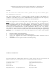
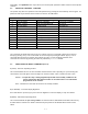
A Page Summary of DO-160C Environmental Testing for Technisonic Model TDFM-136, VHF Digital Transceiver Conditions Section Description of Conducted Tests Temperature and Altitude 4.0 Equipment tested to categories B2 and D1. Vibration 8.0 Equipment is tested without shock mounts to categories B, M and N. Magnetic Effect 15.0 Equipment is class Z. Power Input 16.0 Equipment tested to category B. Voltage Spike 17.0 Equipment tested to category B. RF Emission 21.
B page SECTION 1 GENERAL DESCRIPTION 1.1 INTRODUCTION This publication provides operating and installation information on the TDFM-136, Digital Transceiver manufactured by Technisonic Industries Limited. The TDFM-136 is Project 25 (P25), P hase 1 compliant. The unit offers digital or conventional analog FM communications over an extended frequency range with selectable channel spacing and is intended for use (in t he U.S.
TDFM-136, P/N 981087-2 (5V) RED display and 5 Volt back lighting. Both P/N's 981087-1 and 981087-2 are always provided with 28 Volt back lighting unless a specific request is made for 5 Volt AC operation. 1.5 TECHNICAL CHARACTERISTICS Specification Characteristic GENERAL Model Designation: TDFM-136 Frequency Range: 136.000 to 174.000 MHz Operating Modes: P25 CAI and conventional analog 12.5/25 kHz conventional analog 12 KBPS FSK, 9.6 KBPS C4FM Channel Spacing: 25 or 12.
Display Colour: Green (standard) or Red (specify) NVG Optional DPL is a trademark of Motorola Corporation 1.5 TECHNICAL CHARACTERISTICS (continued) MAIN RECEIVER Sensitivity at 12 dB SINAD -116dBm Adjacent Channel Selectivity -60dB (25 or 12.
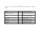
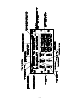
Audio Input 50 mV at 2.5 KHz into 200 S input circuit for ±3.5KHz deviation, adjst. Audio Distortion Less than 5% SECTION 2 OPERATING INSTRUCTIONS 2.1 OPERATING FEATURES The Technisonic TDFM-136 airborne FM transceiver is visually similar to the industry standard TFM138, a two line by 24 character display is centered at the top of the unit, just below the display are six user controls on the left and a 12 key keypad on the right (refer to Figure 2-1). The TDFM-136 support the following features: 1. 2.
2-2
2.3 FIGURE 2-1 DISPLAY INFORMATION Operator's Switches and Controls - TDFM-136 The display is divided into two (2) lines, the upper line displays information pertaining to the MAIN channel, the lower line displays information about the GUARD channel. The information displayed is similar for both the MAIN and GUARD and is formatted out as follows: (refer to figure 2-1).
and holding – the SQUELCH button. Upon release, the saved squelch parameters will be restored to the respective channels. 2.5 OPERATOR COMMANDS - OVERVIEW The operator may affect the operation of the radio parameters by pressing the associated key on the keypad. The parameters that may be affected in this manner are shown in the table below.
2.6 USING OPERATOR DIRECT COMMANDS (Level 1) - continued Upon selecting this command the cursor will appear at the MODE position, the forward arrow (6) key allows the user to scroll through the available modes one at a time. see the table below. Table 2.2 Operating Modes Channel Operating Mode Indicator Analog Wide (25 kHz) ‘w’ Analog Narrow (12.5 kHz) ‘n’ Digital (12.5 kHz) ‘D’ ‘ENTER’ – accepts this entry and returns. ‘ESC’ - abandons the entry and returns.
2.6 USING OPERATOR DIRECT COMMANDS (Level 1) - continued NOTE: Squelch modes available will depend on operating mode chosen. ie. analog modes will not offer P25 talkgroup as an option. Table 2.3 Receive and Transmit Squelch Modes Squelch Mode Receive Transmit carrier Rx Tx noise Rn - (Tx) CTCSS Tones Rt Tt DCS Codes Rc Tc P25 Talkgroup Rg Tg Enter a key number pertaining to the Squelch mode chosen, refer to the tables below. ‘ENTER’ – accepts this entry. ‘ESC’ - abandons the entry.
Table 2.5 CTCSS Tones Tone Key Number 67.0 1 69.3 2 71.9 3 74.4 4 77.0 5 79.7 6 82.5 7 85.4 8 88.5 9 91.5 10 94.8 11 97.4 12 100.0 13 103.5 14 107.2 15 110.9 16 114.8 17 118.8 18 123.0 19 127.3 20 131.8 21 136.5 22 141.3 23 146.2 24 151.4 25 156.7 26 162.2 27 167.9 28 173.8 29 179.9 30 186.2 31 192.8 32 203.5 33 206.5 40 210.7 34 218.1 35 225.7 36 229.1 41 233.6 37 241.8 38 250.3 39 254.
2.6 USING OPERATOR DIRECT COMMANDS (Level 1) - continued 0 (PROG) - Menu Level Up Pressing this key selects the next Higher Menu Level, the Menu Level is indicated in the 4 th character position on the lower row of the display. The Menu Level is indicated in subscript and is as follows: Table 2.
2.7 USING OPERATOR PROGRAMMING COMMANDS (Level 2) Access the Operator Programming Command Level (level 2) by pressing the ‘PROG’ key from the Operator Direct Command Level (level1) once. The Menu Level is indicated in the 4 th character position on the lower row of the display, this will indicate a subscript ‘2’.
4 – Fast Guard Program This command transfers the displayed main memory positions’ parameters to the Guard Memory position according to the position of the G1/G2 front panel switch. The selected Guard channel will now contain the information from the selected Main channel memory. This feature may be disabled via Maintenance Command (Level 3) ‘4’. ‘ENTER’ – accepts this transfer. ‘ESC’ - abandons the transfer. 5 – Scan Mode: ON/OFF This command allows the user to start and stop the Scan operation.
9 – not currently used - reserved 0 (PROG) - Menu Level Up Pressing this key selects the next Higher Menu Level, the Menu Level is indicated in the 4 th character position on the lower row of the display. The Menu Level is indicated in subscript and is as follows: Table 2.
2.8 USING MAINTENANCE COMMANDS (Level 3) The Maintenance Command Level is available to allow configuration and testing of the radio in a bench test environment. This command level may be disabled by removing the jumper Jn on the MCU board. NOTE: this command level should NOT BE ENABLED when the radio is installed in the airframe.
9 – Terminal Mode Put the TDFM-136 into Terminal Mode. This is a bench test mode and allows the maintenance personnel to control the radio for testing. ‘ESC’ - abandons Terminal Mode and returns.
3.1 GENERAL This section contains information and instructions for the correct installation of the TDFM136, VHF/FM Digital Transceiver. Make certain that the correct frequencies are preprogrammed in accordance with the equipment user's valid FCC operator's license, prior to installation. 3.2 EQUIPMENT PACKING LOG Unpack the equipment and check for any damage that may have occurred during transit. Save the original shipping container for returns due to damage or warranty claims.
FIGURE 3-1 3.
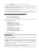
TDFM-136 Transceiver 15-Pin D Connections Pin # Description 1 600 Ohm Output 2 Data Output 3 Panel Lighting (28VDC or 5VAC) 4 Memory UP/PC Download Input 5 Memory Down/PC Download Input 6 Mic Signal Input 7 Main Power +28VDC 8 Main Ground 9 4 ohm Speaker Output 10 4 ohm/600 ohm Output Ground 11 Data Input 12 PC Download Input 13 PTT (Ground Keying) 14 Main Power +28VDC 15 Main Ground TABLE 3-1 3.
Figure 3-2 Wiring Connections for TDFM-136 Transceiver 3-4
3.7.4 Front Panel Back Lighting Front panel back lighting connection should be made on pin 3 of the transceiver. The opposite end of this lead should be connected to the panel lighting system of the aircraft. Before connecting, verify the required panel lighting voltage (28 VDC or 5VAC) on the transceiver configuration control label. 3.7.5 Audio Outputs (600 ohms and 4 0hms) The audio output from pin 9 can be used to drive a 4 ohm speaker up to 2.5 watts. Audio output from pin 1 is 600 ohms, 0.
3.8 3.9 TRANSMITTER SIDETONE LEVEL ADJUSTMENT 1. Set the transceiver operating frequency to 155.000 MHz and connect an appropriate test receiver to the RF output connector. Ensure that the output of the transceiver is terminated into a proper dummy load. 2. Key the transmitter and input a -10 dBm (0.25 VRMS), 1 KHz audio signal into the microphone input. 3. Select the sidetone adjust command and then adjust the sidetone level using the guard volume control to produce a +3.0 dBm (1.