
Instruction Manual


2-3
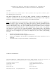
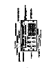
FIGURE 2-1 Operator's Switches and Controls - TDFM-136
2.3 DISPLAY INFORMATION
The display is divided into two (2) lines, the upper line displays information pertaining to the MAIN channel, the
lower line displays information about the GUARD channel. The information displayed is similar for both the MAIN
and GUARD and is formatted out as follows: (refer to figure 2-1).
The first three characters of the display indicate the CHANNEL selected, for MAIN the allowable values are 001
to 250, for GUARD only GD1 or GD2 can be displayed.
The fourth character indicates the SCAN list status of the channel, this is true for the MAIN channel only. If the
selected channel is included in a scan list, then the scan list number (1-5) will be displayed in subscript.
The next nine (9) characters are spaces for a text DESCRIPTION of the channel.
The next character indicates the operating MODE of the radio as follows:
lower case 'w' indicates analog wide mode
lower case 'n' indicates analog narrow mode
upper case 'D' indicates project 25 digital operation.
The next eight (8) characters indicate the channel frequency in MHz. The final two (2) characters indicate the
SQUELCH mode and operation as follows:
For Receive Operation
Rx indicates no squelch mode has been chosen
Rt indicates that CTCSS tones are being used
Rc indicates that DCS codes are being used
Rg indicates that project 25 TALK GROUPS are being used
Rn indicates that NOISE Squelch is being used.
For Transmit Operation
Tx indicates no squelch mode has been chosen
Tt indicates that CTCSS tones are being used
Tc indicates that DCS codes are being used
Tg indicates that project 25 TALK GROUPS are being used
there is no noise squelch mode for transmit!
2.4 BASIC RADIO OPERATION
Upon turning on the radio, after the boot sequence is finished the operator sees a two line display the top line of
which presents the operating parameters of the main channel, the bottom line of which presents the operating
parameters of the chosen guard channel.
The operator can receive signals from two (2) sources simultaneously: the selected MAIN receive (Rx) frequency
and the selected GUARD Rx frequency.
The operator may transmit on one (1) frequency at a time, the transmit (Tx) frequency is determined by the position
of the MN/GD switch. If set to ‘MN’ then the unit will transmit on the Tx frequency of the selected MAIN channel.
If the MN/GD switch is set to ‘GD’ then the unit will transmit on the Tx frequency of the selected GUARD channel.
The display will alter – on the appropriate line - to display the Tx frequency and squelch mode when the user
presses the press-to-talk (PTT) switch.
The operator selects the guard channel used via the front panel GD1/GD2 switch. Transmit occurs at a power level
as determined by the position of the HI/LO power switch: HI is 10 watts, LO is 1 watt.
The user may cause the radio to defeat the squelch on both selected MAIN and GUARD channels by pressing –