OPERATING INSTRUCTIONS FOR Model 3300PB Percent Oxygen Analyzer SERIES 3300 PERCENT OXYGEN SPAN SPAN SAMPLE Teledyne Analytical Instruments DANGER HIGHLY TOXIC AND OR FLAMMABLE LIQUIDS OR GASES MAY BE PRESENT IN THIS MONITORING SYSTEM. PERSONAL PROTECTIVE EQUIPMENT MAY BE REQUIRED WHEN SERVICING THIS SYSTEM. HAZARDOUS VOLTAGES EXIST ON CERTAIN COMPONENTS INTERNALLY WHICH MAY PERSIST FOR A TIME EVEN AFTER THE POWER IS TURNED OFF AND DISCONNECTED.
Copyright © 1999 Teledyne Analytical Instruments All Rights Reserved. No part of this manual may be reproduced, transmitted, transcribed, stored in a retrieval system, or translated into any other language or computer language in whole or in part, in any form or by any means, whether it be electronic, mechanical, magnetic, optical, manual, or otherwise, without the prior written consent of Teledyne Analytical Instruments, 16830 Chestnut Street, City of Industry, CA 91749-1580.
Contents Introduction 1.1 1.2 1.3 1.4 Overview ........................................................................ Main Features of the Analyzer ....................................... Front Panel Description .................................................. Rear Panel Description .................................................. 1-1 1-1 1-2 1-3 Operational Theory 2.1 Introduction .................................................................... 2-1 2.2 Micro-Fuel Cell Sensor ..................
.4 Setting the Alarm Setpoints............................................ 4-3 4.4.1 Alarm 1 .................................................................. 4-3 4.4.2 Alarm 2 .................................................................. 4-3 4.4.3 Sensor Fail Alarm .................................................. 4-4 4.5 Selecting a Fixed Range or Autoranging ....................... 4-4 4.6 Calibration ..................................................................... 4-4 Maintenance 5.
DANGER COMBUSTIBLE GAS USAGE WARNING This is a general purpose instrument designed for usage in a nonhazardous area. It is the customer's responsibility to ensure safety especially when combustible gases are being analyzed since the potential of gas leaks always exist. The customer should ensure that the principles of operating of this equipment is well understood by the user.
Model 3300PB complies with all of the requirements of the Commonwealth of Europe (CE) for Radio Frequency Interference, Electromagnetic Interference (RFI/EMI), and Low Voltage Directive (LVD).
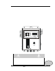
Percent Oxygen Analyzer Introduction 1 Introduction 1.1 Overview The Teledyne Electronic Technologies Analytical Instruments (TETAI) Model 3300PB is a microprocessor-based percent oxygen analyzer for realtime measurement of the percent of oxygen in inert gases, or in a wide variety of gas mixtures. It features simple operation, fast response, and a compact, rugged construction. Typical applications of the Model 3300PB are monitoring nitrogen generators and inert gas blanketing applications. 1.
1 Introduction • • • • • Model 3300PB Operator can select Autoranging, which allows the analyzer to automatically select the proper preset range for a given measurement, or he can lock the analyzer onto a single range. Two concentration alarms with adjustable setpoints. Sensor failure alarm. Three analog outputs: two for measurement (0–10 V dc, and negative ground 4–20 mA dc) and one for range identification (0-10 V dc). Compact and rugged Control Unit, wall mounted NEMA-4 rated enclosure. 1.
Percent Oxygen Analyzer • Introduction 1 Set Alarm 2 Set the Alarm 2 Hi or Low, and the concentration to which alarm 2 activates. • Set HI Range Set the high analysis range for the instrument (up to 0-25 %). • Set LO Range Set the low analysis range for the instrument (down to 0-1 %). • Span Span calibrate the analyzer.
1 Introduction 1-4 Model 3300PB • Power Connection • Analog Outputs • Alarm Connections • Sensor Connector AC version: 100–240 V ac, at 50/60Hz. The connector housing includes the fuse holder and the power switch. Fuse Holder: Replacing the fuse is described in Chapter 5, Maintenance. I/O Power Switch: Turns the instrument power ON (1) or OFF (0). 0–10 V dc concentration output. 0–10 V dc range ID (or optional overrange) output. 4–20 mA dc concentration output, negative ground.
Percent Oxygen Analyzer Operational Theory 2 Operational Theory 2.1 Introduction The analyzer is composed of two subsystems: 1. Analysis Unit with Micro-Fuel Cell Sensor 2. Control Unit with Signal Processing, Display and Controls The Analysis Unit is designed to accept the sample gas and direct it to the sensitive surface of the Micro-Fuel Cell sensor. The Micro-Fuel Cell is an electrochemical galvanic device that translates the amount of oxygen present in the sample into an electrical current.
2 Operational Theory Model 3300PB Micro-Fuel Cell is therefore a hybrid between a battery and a true fuel cell. (All of the reactants are stored externally in a true fuel cell.) 2.2.2 Anatomy of a Micro-Fuel Cell The Micro-Fuel Cell is made of extremely inert plastic (which can be placed confidently in practically any environment or sample stream). It is effectively sealed, though one end is permeable to oxygen in the sample gas.
Percent Oxygen Analyzer Operational Theory 2 conductor connecting them, through some electrical circuitry, to one of the external contacts in the connector receptacle, which is on the top of the cell. 2.2.3 Electrochemical Reactions The sample gas diffuses through the Teflon membrane.
2 Operational Theory Model 3300PB external current, will increase, even though the proportion of oxygen has not changed. Fortunately, Dalton's Law confirms that every gas in a mixture contributes the same pressure to the mixture that it would exert if it were alone in the same amount in that same volume. This means that as long as the total pressure of the sample remains constant, the mixture can change, but the diffusion of the oxygen will be affected only by the concentration of the oxygen.
Percent Oxygen Analyzer 2.3 Operational Theory 2 Electronics 2.3.1 General The signal processing uses an Intel microcontroller with on-board RAM and ROM to control all signal processing, input/output, and display functions for the analyzer. System power is supplied from a universal power supply module designed to be compatible with most international power sources. The power supply circuitry is on the Power Supply PCB, which is mounted vertically, just behind the rear panel of the Control Unit.
2 Operational Theory Model 3300PB In the presence of oxygen the cell generates a current. The sensor has an internal thermistor compensation network. The output of the sensor is converted to voltage millivolt range. This output is fed to a volatge amplifier. The internal thermistor network provides temperature compensation of the sensor output. The resistance of the network changes with temperature, compensating for the changes of the microfuel cell output to temperature.
Percent Oxygen Analyzer Installation 3 Installation Installation of the analyzer includes: 1. Unpacking the system. 2. Mounting the Control Unit to a wall 3. Installing the Micro-Fuel Cell 4. Making the electrical connections. 5. Making the gas connections. 6. Testing the installation. CAUTIONS: Read this chapter in its entirety before installing the units. For indoor use only. The Sample must be free of entrained solids or water.
3 Installation 3.2 Model 3300PB Location and Mounting 3.2.1 Control Unit Installation The 3300PB Control Unit is designed to be wall-mounted, in a general purpose, area. The unit should be installed at viewing level in a sheltered area. Refer to the Outline diagram D-69220 for the physical dimensions of the analyzer. 3.2.2 Installing the Micro-Fuel Cell A Micro-Fuel Cell is included as a separate item. It must be installed prior to instrument use.
Percent Oxygen Analyzer Installation 3 Primary Input Power: The power strip supplied inside the analyzer. Connect ground to terminal 1, neutral to terminal 3, and hot to terminal 2. Make sure female plug end is inserted in the control unit power receptacle. The universal power supply allows direct connection to any 100-240 VAC, 50/60Hz power source. The fuse block, to the right of the power cord receptacle, accepts two 5x20mm 0.5 A, 250V,time-lag (T) fuse. (See Fuse Replacement in chapter 5, Maintenance.
3 Installation Model 3300PB The alarm relay circuits are designed for failsafe operation, meaning the relays are energized during normal operation. If power fails the relays deenergize (alarms activated). The contact connections are indicated diagrammatically on the rear panel as Normally Closed, Common, and Normally Open. Figure 3-2 explains how these act in failsafe operation. Alarm ! and Alarm 2 can both be configured as either HI or LO.
Percent Oxygen Analyzer Installation 3 3.3.1 RS-232 Port Option The digital signal output is a standard RS-232 serial communications port used to connect the analyzer to a computer, terminal, or other digital device. The pinouts are listed in Table 1. Table 1: RS-232 Signals RS-232 Sig RD TD COM RS-232 Pin 2 3 5 Purpose Received Data Transmitted Data Common The data sent is status information, in digital form, updated every two seconds.
3 Installation Model 3300PB A switching valve is provided to feed the analysis unit with either sample or gas. A flowmwter and flow controller valve are part of the system and will assist in setting the flow of the gas. Sample flow should be adjusted to 2 SCFH. The sample vent connection should not restrict the sample flow. The sensor is designed to operate at atmospheric pressure. Restricting the sample vent line will result in pressurizing the sensor and altering the O2 reading.
Percent Oxygen Analyzer Installation 3 3.4.1 Vacuum Service Option For vacuum service pluming reference figure 3-4. The vacuum service option is recommended for applications in which the sample source is not pressurized. The customer must supply a pump and bypass system to complete the sample system. The sample inlet and outlet pressure must be maintained at a constant pressure for proper performance.
3 Installation 3.5 Model 3300PB Installation Checklist Before connecting the instrument to the power source and turning it on, make sure you have: • Correctly installed the Sample and Exhaust gas lines • Opened the isolation valves • Checked for leaks • Set the sample pressure to 5–10 psig (34.5-68.9 Kpa), nominal (for non-vacuum service units) • Set the flow Once the above checks have been made, you can connect to the power source. The instrument is now ready for operation.
Percent Oxygen Analyzer Operation 4 Operation 4.1 Introduction Once the analyzer has been mounted, the gas lines connected and the electrical connections made, the Analyzer can be configured for your application. This involves setting the system parameters: • Defining the user selectable analysis ranges. • Setting alarm setpoints. • Calibrating the instrument. All of these functions are performed via the front panel controls, shown in Figure 4-1.
4 Operation 4.2 Model 3300PB Using the Function and Data Entry Buttons When no buttons on the Analyzer are being pressed, the instrument is in the Analyze mode. It is monitoring the percent of oxygen in the sample gas that is flowing through the Remote Probe. When one of the Function Buttons is being pressed, the Analyzer is in the Setup mode or the Calibration mode.
Percent Oxygen Analyzer Operation 4 4.3.1 HI Range Setting the HI Range fullscale value defines the LEAST sensitive analysis range to be used. To set the HI Range: 1. Press the SET HI RANGE Function button once. 2. Immediately (within 5 seconds) press either the ∆ or ∇ button to raise or lower the displayed value, as required, until the display reads the desired fullscale percent concentration. 4.3.2 LO Range Setting the LO Range fullscale value defines the MOST sensitive range to be used.
4 Operation Model 3300PB until the display reads the desired percent concentration. (if within 5 seconds no key is pressed, the instrument will return to the sample mode and display oxygen concentration). After setting the value wait for the unit to time out of this mode (approximately 5 seconds) and return to displaying oxygen concentration. 4.4.2 Set Alarm 2 Alarm 2 can be set either as a high or low alarm. To configure this alarm to your preferences: 1. Press the SET ALARM 2 function button once. 2.
Percent Oxygen Analyzer 4.5 Operation 4 Selecting a Fixed Range or Autoranging The Model 3300PB can operate in fixed high, fixed low, or autoranging mode. To change modes: 1. Press and then release the SET HI RANGE and the SET LO RANGE buttons simultaneously. 2. Immediately (within 5 seconds) press either the ∆ or ∇ button until Auto, Lo, or Hi displays on the LCD, as desired. After about three seconds, the analyzer resumes monitoring in the selected range mode. 4.
4 Operation Note: Model 3300PB When you stop pressing the UP/DOWN keys, the rapid flashing will cease and the new span value will be acquired by the analyzer after five seconds. The alarms will only be nonresponsive for 60 seconds. This timeframe allows you to reintroduce sample gas into the analyzer. 5. Immediately flow sample into the analyzer.
Percent Oxygen Analyzer Maintenance 5 Maintenance Aside from normal cleaning and checking for leaks at the gas connections, the Model 3300PB should not require any maintenance beyond replacement of expended Micro-Fuel Cells, and perhaps a blown fuse. Routine maintenance includes occasional recalibration, as described in chapter 4, Operation. 5.1 Replacing the Fuse Remove Power to Unit before replacing the fuse.
5 Maintenance Model 3300PB fuse holder will slide out. There are two fuses in use and are visible in the clip. 4. Remove the bad fuse and replace it with a 0.5A, 250VAC, 5x20mm IEC, time lag (T) fuse (P /N F1130). 5. Replace the fuse holder into its receptacle, pushing in firmly until it clicks. 5.2 Sensor Installation or Replacement 5.2.1 When to Replace a Sensor The Micro-Fuel Cell typically provide almost constant output through their useful life, and then fall off sharply towards zero at the end.
Percent Oxygen Analyzer WARNING: Maintenance 5 The sensor used in the Model 3300PB uses electrolytes which contain substances that are extremely harmful if touched, swallowed, or inhaled. Avoid contact with ANY fluid or powder in or around the unit. What may appear to be plain water could contain one of these toxic substances. In case of eye contact, immediately flush eyes with water for at least 15 minutes. Call physician. (See Appendix, Material Safety Data Sheet—MSDS). 5.2.
5 Maintenance Model 3300PB 5.2.5 Cell Warranty Conditions The Class I-22 Micro-Fuel cell is used in the Model 3300PB. This cell is a long life cell and is warranted for 2 years (under specified operating conditions— see Appendix) from the date of shipment. Note any Addenda attached to the front of this manual for special information applying to your instrument. With regard to spare cells, warranty period begins on the date of shipment.
Percent Oxygen Analyzer Appendix Appendix A.1 Specifications Ranges: Signal Output: Range ID: Display: Alarms: System Operating Temp: Accuracy: Response Time: System Power Requirements: System Enclosure: Weight: Sensor Type: 0-3 % and 0-10 % oxygen (Standard Ranges), and 0-25 % (nominal) Calibration Range. User selectable % Ranges can be set between 1% and 25 % oxygen (optional 100% range). Voltage: 0–10 V dc, negative ground Current: 4-20 mA, negative ground 0-10 V dc. Light emitting diode display.
Appendix Model 3300PB A.2 Spare Parts List QTY. 1 1 1 1 2 P/N C-65220E C-65220F C-64586C C-44611-I-22 F-1130 1 F-274 IMPORTANT: DESCRIPTION PC Board, Main PC Board, Main for 0-100% range. PC Board, Power Supply, AC Version Micro-Fuel Cell, I-22 Fuse (AC), ½A, 250 VAC, IEC Type T, 5 x 20mm Flowmeter 0.3-3.0 SCFH Orders for replacement parts should include the part number and the model and serial number of the system for which the parts are intended.
Percent Oxygen Analyzer Appendix A.3 Reference Drawing A-69265 Piping Diagram D-69229 Outline Diagram A.4 Miscellaneous The symbol: ~ is used on the rear panel of the model 3300PB to signify volts alternating current (V ac). NOTE: The MSDS on this material is available upon request through the Teledyne Environmental, Health and Safety Coordinator.
Appendix A-4 Model 3300PB Teledyne Analytical Instruments
Percent Oxygen Analyzer A.5 Appendix Material Safety Data Sheet Section I – Product Identification Product Name: Manufacturer: Address: Phone: Technical Support: Environment, Health and Safety: Date Prepared : Micro-Fuel Cells Mini-Micro-Fuel Cells, all classes Super Cells, all classes except T–5F Electrochemical Oxygen Sensors, all classes.
Appendix Model 3300PB Section III – Physical Hazards Potential for fire and explosion: The electrolyte in the Micro-Fuel Cells is not flammable. There are no fire or explosion hazards associated with Micro-Fuel Cells. Potential for reactivity: The sensors are stable under normal conditions of use. Avoid contact between the sensor electrolyte and strong acids.
Percent Oxygen Analyzer Appendix Section V – Emergency and First Aid Procedures Eye Contact: Skin Contact: Ingestion: Inhalation: Flush eyes with water for at least 15 minutes and get immediate medical attention. Wash affected area with plenty of water and remove contaminated clothing. If burning persists, seek medical attention. Give plenty of cold water. Do not induce vomiting. Seek medical attention. Do not administer liquids to an unconscious person. Liquid inhalation is unlikely.