
INSTRUCTION MANUAL NEMA OZONE MONITOR 460H
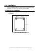

2.2 Pneumatic Connections
1. Connect a ¼” exhaust line to the fitting labeled ‘Exhaust.’ This line should be vented
to an outside area, since the exhaust gas may still contain trace levels of ozone that may
not be completely removed by the built-in the ozone scrubber.
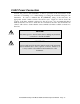
CAUTION
Exhaust gas from the M460H may contain dangerous levels of
ozone!
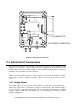
2. Connect the ozone delivery line to the ¼” inlet fitting labeled “Ozone Inlet” on the
bottom face of the enclosure (See Figure 2-2.) The ozone delivery should be
regulated to no more than 30psig. All tubing used should be made of ozone resistant
material such as PTFE(Teflon™) or FEP. API can supply appropriate tubing for
connecting the ozone supply line.
3. Connect the oxygen or other zero gas source to the ¼” tube fitting labeled ‘Zero Gas
Inlet.’ Zero Gas supply pressure should be regulated between 5 and 30 psig.
4. The gas flow rate through the monitor should be established between 0.5 and 2.0
L/min.
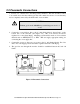
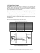
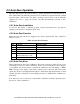
Figure 2-2 Pneumatic Connections
WARNING - DO NOT EXCEED
30 PSIG GAS DELIVERY
PRESSURE
OZONE INLET
WARNING - DO NOT EXCEED
30 PSIG GAS DELIVERY
PRESSURE
ZERO GAS INLET
WARNING - THIS GAS MAY
CONTAIN HARMFUL LEVELS
OF OZONE
EXHAUST
P/N 03662D Teledyne API Model 460H O
3
Monitor Operator Manual - Page 12