GE863-QUAD GE863-PY Hardware User Guide 1vv0300715 Rev.
GE863-QUAD GE863-PY 1vv0300715 Rev. 1 - 19/09/06 Contents 1 Overview ...........................................................................................................................6 2 GE863 module connections ............................................................................................7 3 2.1 PIN-OUT...................................................................................................................................7 2.2 PINS LAYOUT...........................
GE863-QUAD GE863-PY 1vv0300715 Rev. 1 - 19/09/06 7.4 Microphone Biasing ................................................................................................................36 7.4.1 7.4.2 7.5 Microphone Buffering .............................................................................................................39 7.5.1 7.5.2 8 Buffered Balanced Mic...................................................................................................................
GE863-QUAD GE863-PY 1vv0300715 Rev. 1 - 19/09/06 12 Camera ............................................................................................................................60 12.1 12.1.1 12.1.2 12.1.3 12.1.4 12.1.5 Transchip Camera ..............................................................................................................60 Camera Interface Connectors........................................................................................................
GE863-QUAD GE863-PY 1vv0300715 Rev. 1 - 19/09/06 This document is relating to the following products: GE863-QUAD Pb free GE863-PY Pb free 3 990 250 662 3 990 250 661 Reproduction forbidden without Telit Communications S.p.A.
GE863-QUAD GE863-PY 1vv0300715 Rev. 1 - 19/09/06 1 Overview The aim of this document is the description of some hardware solutions useful for developing a product with the Telit GE863-QUAD/PY module. In this document all the basic functions of a mobile phone will be taken into account; for each one of them a proper hardware solution will be suggested and eventually the wrong solutions and common errors to be avoided will be evidenced.
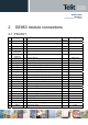
GE863-QUAD GE863-PY 1vv0300715 Rev. 1 - 19/09/06 2 GE863 module connections 2.1 PIN-OUT Pin Signal 1 GPIO13 I/O GPIO13 CMOS 2.8V 2 GPIO12 I/O GPIO12 CMOS 2.8V 3 GPIO11 I/O GPIO11 CMOS 2.8V 4 GPIO10 I/O GPIO10 CMOS 2.8V 5 I/O GPIO9 / CAM_RST (2) CMOS 2.8V I/O GPIO8 / CAM_ON (2) CMOS 2.8V 7 GPIO9 / CAM_RST GPIO8 / CAM_ON CAM_CLK I/O Camera clock (2) CMOS 2.
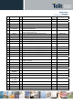
GE863-QUAD GE863-PY 1vv0300715 Rev. 1 - 19/09/06 Pin Signal 28 GND 29 STAT_LED 30 AXE I Handsfree switching 31 VAUX1 - Power output for external accessories (camera) 32 33 GPIO4 / CAM_SDA GPIO2 / JDR 34 GPIO1 35 CHARGE 36 GND - Ground 37 C103/TXD I Serial data input (TXD) from DTE 38 C104/RXD O Serial data output to DTE CMOS 2.8V 39 C108/DTR I CMOS 2.8V 40 C105/RTS I 41 C106/CTS O Output for Clear to send signal (CTS) to DTE CMOS 2.
GE863-QUAD GE863-PY 1vv0300715 Rev. 1 - 19/09/06 Pin Signal 59 GPIO17 I/O GPIO CMOS 2.
GE863-QUAD GE863-PY 1vv0300715 Rev. 1 - 19/09/06 2.2 PINS LAYOUT Reproduction forbidden without Telit Communications S.p.A.
GE863-QUAD GE863-PY 1vv0300715 Rev. 1 - 19/09/06 3 Hardware Commands 3.1 Turning ON the GE863-QUAD/PY To turn on the GE863-QUAD/PY the pad ON# must be tied low for at least 1 second and then released. The maximum current that can be drained from the ON# pad is 0,1 mA. A simple circuit to do it is: ON# R1 Q1 Power ON impulse R2 GND NOTE: don't use any pull up resistor on the ON# line, it is internally pulled up.
GE863-QUAD GE863-PY 1vv0300715 Rev. 1 - 19/09/06 1- Let's assume you need to drive the ON# pad with a totem pole output of a +3/5 V microcontroller (uP_OUT1): 2- Let's assume you need to drive the ON# pad directly with an ON/OFF button: 3.2 Turning OFF the GE863-QUAD/PY The turning off of the device can be done in two ways: Reproduction forbidden without Telit Communications S.p.A.
GE863-QUAD GE863-PY 1vv0300715 Rev. 1 - 19/09/06 • by software command (see GE863-QUAD/PY Software User Guide) • by hardware shutdown When the device is shut down by software command or by hardware shutdown, it issues to the network a detach request that informs the network that the device will not be reachable any more. 3.2.1 Hardware shutdown To turn OFF the GE863-QUAD/PY the pad ON# must be tied low for at least 1 second and then released. The same circuitry and timing for the power on shall be used.
GE863-QUAD GE863-PY 1vv0300715 Rev. 1 - 19/09/06 NOTE: don't use any pull up resistor on the RESET# line nor any totem pole digital output. Using pull up resistor may bring to latch up problems on the GE863-QUAD/PY power regulator and improper functioning of the module. The line RESET# must be connected only in open collector configuration. TIP: The unconditional hardware reboot should be always implemented on the boards and software should use it as an emergency exit procedure.
GE863-QUAD GE863-PY 1vv0300715 Rev. 1 - 19/09/06 4 Power Supply The power supply circuitry and board layout are a very important part in the full product design and they strongly reflect on the product overall performances, hence read carefully the requirements and the guidelines that will follow for a proper design. 4.
GE863-QUAD GE863-PY 1vv0300715 Rev. 1 - 19/09/06 4.2 General Design Rules The principal guidelines for the Power Supply Design embrace three different design steps: - the electrical design - the thermal design. - the PCB layout. 4.2.1 Electrical design Guidelines The electrical design of the power supply depends strongly from the power source where this power is drained.
GE863-QUAD GE863-PY 1vv0300715 Rev. 1 - 19/09/06 An example of linear regulator with 5V input is: 4.2.1.2 + 12V input Source Power Supply Design Guidelines • • • • • • • The desired output for the power supply is 3.8V, hence due to the big difference between the input source and the desired output, a linear regulator is not suited and shall not be used. A switching power supply will be preferable because of its better efficiency especially with the 2A peak current load represented by the GE863-QUAD/PY.
GE863-QUAD GE863-PY 1vv0300715 Rev. 1 - 19/09/06 An example of switching regulator with 12V input is: 4.2.1.3 Battery Source Power Supply Design Guidelines • The desired nominal output for the power supply is 3.8V and the maximum voltage allowed is 4.2V, hence a single 3.7V Li-Ion cell battery type is suited for supplying the power to the Telit GE863-QUAD/PY module. The three cells Ni/Cd or Ni/MH 3,6 V Nom.
GE863-QUAD GE863-PY 1vv0300715 Rev. 1 - 19/09/06 4.2.1.4 Battery Charge control Circuitry Design Guidelines The charging process for Li-Ion Batteries can be divided into 4 phases: • Qualification and trickle charging • Fast charge 1 - constant current • Final charge - constant voltage or pulsed charging • Maintenance charge The qualification process consists in a battery voltage measure, indicating roughly its charge status.
GE863-QUAD GE863-PY 1vv0300715 Rev. 1 - 19/09/06 As you can see, the charging process is not a trivial task to be done; moreover all these operations should start only if battery temperature is inside a charging range, usually 5°C - 45°C.
GE863-QUAD GE863-PY 1vv0300715 Rev. 1 - 19/09/06 4.2.3 Power Supply PCB layout Guidelines As seen on the electrical design guidelines the power supply shall have a low ESR capacitor on the output to cut the current peaks and a protection diode on the input to protect the supply from spikes and polarity inversion. The placement of these components is crucial for the correct working of the circuitry. A misplaced component can be useless or can even decrease the power supply performances.
GE863-QUAD GE863-PY 1vv0300715 Rev. 1 - 19/09/06 5 Antenna The antenna connection and board layout design are the most important part in the full product design and they strongly reflect on the product overall performances, hence read carefully and follow the requirements and the guidelines for a proper design. 5.
GE863-QUAD GE863-PY 1vv0300715 Rev. 1 - 19/09/06 This device is to be used only for mobile and fixed application. The antenna(s) used for this transmitter must be installed to provide a separation distance of at least 20 cm from all persons and must not be co-located or operating in conjunction with any other antenna or transmitter. End-Users must be provided with transmitter operation conditions for satisfying RF exposure compliance.
GE863-QUAD GE863-PY 1vv0300715 Rev. 1 - 19/09/06 • • MODEM SERIAL PORT MODEM SERIAL PORT 2 (DEBUG) 6.1 MODEM SERIAL PORT Several configurations can be designed for the serial port on the OEM hardware, but the most common are: • RS232 PC com port • microcontroller UART @ 2.8V - 3V (Universal Asynchronous Receive Transmit) • microcontroller UART@ 5V or other voltages different from 2.
GE863-QUAD GE863-PY 1vv0300715 Rev.
GE863-QUAD GE863-PY 1vv0300715 Rev. 1 - 19/09/06 6.2 MODEM SERIAL PORT 2 (Python Debug) It is available on the following pins: PIN # 25 26 NAME TX_TRACE RX_TRACE DESCRIPTION TX Data RX Data TYPE CMOS 2.8V CMOS 2.8V 6.3 RS232 level translation In order to interface the Telit GE863-QUAD/PY with a PC com port or a RS232 (EIA/TIA-232) application a level translator is required.
GE863-QUAD GE863-PY 1vv0300715 Rev. 1 - 19/09/06 NOTE: In order to be able to do in circuit reprogramming of the GE863-QUAD/PY firmware, the serial port on the Telit GE863-QUAD/PY shall be available for translation into RS232 and either it's controlling device shall be placed into tristate, disconnected or as a gateway for the serial data when module reprogramming occurs. Only RXD, TXD, GND and the On/off module turn on pad are required to the reprogramming of the module, the other lines are unused.
GE863-QUAD GE863-PY 1vv0300715 Rev. 1 - 19/09/06 The RS232 serial port lines are usually connected to a DB9 connector with the following layout: 6.4 5V UART level translation If the OEM application uses a microcontroller with a serial port (UART) that works at a voltage different from 2.8 - 3V, then a circuitry has to be provided to adapt the different levels of the two set of signals.
GE863-QUAD GE863-PY 1vv0300715 Rev. 1 - 19/09/06 and for a 5V receiver: NOTE: The UART input line TXD (rx_uart) of the GE863-QUAD/PY is NOT internally pulled up with a resistor, so there may be the need to place an external 47KΩ pull-up resistor, either the DTR (dtr_uart) and RTS (rts_uart) input lines are not pulled up internally, so an external pull-up resistor of 47KΩ may be required. A power source of the internal interface voltage corresponding to the 2.
GE863-QUAD GE863-PY 1vv0300715 Rev. 1 - 19/09/06 7 Audio Section Overview The Base Band Chip of the GE863-QUAD / PY Telit Module provides two different audio blocks; both in transmit (Uplink) and in receive (Downlink) direction: “MT lines” should be used for handset function, “HF lines” is suited for hands -free function (car kit). These two blocks can be active only one at a time, selectable by AXE hardware line or by AT command.
50cm 7cm 3,3mV rms -45dBV/Pa -45dBV/Pa 0,33mV rms 23mVrms 365mV rms GE863-GPS Audio Paths +10dB +20dB Ear_HF- Ear_HF+ Mic_HF+ Mic_HF- Ear_MT- Mic_MT- Ear_MT+ GM863-GPS Mic_MT+ Single ended Balanced Fully Differential Power Buffers Differential Line-Out Drivers 16 -12dBFS 16 audio2.skd 8 GE863-QUAD GE863-PY 1vv0300715 Rev. 1 - 19/09/06 EXTERNAL AMPLIFIER Reproduction forbidden without Telit Communications S.p.A.
GE863-QUAD GE863-PY 1vv0300715 Rev. 1 - 19/09/06 7.1 Microphone Paths Characteristic and Requirements TIP: being the microphone circuitry the more noise sensitive , its design and layout must be done with particular care. Both microphone paths are balanced and the OEM circuitry should be balanced designed to reduce the common mode noise typically generated on the ground plane. However also an unbalanced circuitry can be used for particular OEM application needs .
GE863-QUAD GE863-PY 1vv0300715 Rev. 1 - 19/09/06 TIP: definition of the nominal sensitivity of the microphone lines . The nominal sensitivity of the microphone lines indicates the voltage level on the GE863-QUAD / PY pins present during "normal spoken" conditions. For a handset , the "normal spoken” conditions take place when the talker mouth is 7cm far from the microphone ; under these conditions the voice will produce an acoustic pressure of -4,7dBPa @1kHz on the microphone membrane .
GE863-QUAD GE863-PY 1vv0300715 Rev. 1 - 19/09/06 TIP: environment consideration . For hands-free/car kit microphone, you must take into account the voice attenuation, due to the distance between the microphone itself and the talker , when designing the external microphone amplifier.
GE863-QUAD GE863-PY 1vv0300715 Rev. 1 - 19/09/06 7.2 General Design Rules There are several configurations for the audio paths, but the most effective difference is between balanced and unbalanced microphone configuration. It is highly recommended to keep the whole microphone path balanced even if this means having 2 wires connecting the microphone instead of one needed (plus ground) in the unbalanced case.
GE863-QUAD GE863-PY 1vv0300715 Rev. 1 - 19/09/06 7.4 Microphone Biasing The electret microphones usually need a biasing voltage to work properly. Refer to your microphone provider for the characteristics required. NOTE: The microphones have a hot wire were the positive biasing must be connected. Usually it is indicated by a + symbol or a red point. If the polarity of the bias is reversed, then the microphone will not work properly. For this reason be sure to respect the mic. biasing polarity. 7.4.
GE863-QUAD GE863-PY 1vv0300715 Rev. 1 - 19/09/06 NOTE: The cable to the microphone should not be shielded, instead a twisted pair cable shall be used. NOTE: The microphone sensitivity changes with the value of R2 and R3. Usually the microphones are characterized with 2kΩ biasing resistance, so try to keep the sum of R2 and R3 around 2kΩ. Refer to your microphone manufacturer for the mic. characteristics. 7.4.
GE863-QUAD GE863-PY 1vv0300715 Rev. 1 - 19/09/06 NOTE: In the unbalanced application the capacitor C3 shall be > 200nF otherwise the frequency response will be cut at low band frequencies (down to 300Hz). This capacitor can be placed close to the MIC- pad (MIC_HF- or MIC_MT- depending on the audio path chosen) or if possible it should be placed close to the shielded cable connector.
GE863-QUAD GE863-PY 1vv0300715 Rev. 1 - 19/09/06 7.5 Microphone Buffering As seen previously, a microphone shall be connected to the input pins of the GE863-QUAD / PY through a buffer amplifier that boosts the signal level to the required value. Again the buffered microphone circuitry can be balanced or unbalanced: where possible it is always preferable a balanced solution. The buffering circuit shall be placed close to the microphone or close to the microphone wire connector. 7.5.
GE863-QUAD GE863-PY 1vv0300715 Rev. 1 - 19/09/06 The buffer gain is given by the formula: Gain = R604 R606 = R605 R607 The C636 and C637 capacitors are placed in order to cut off the gain at higher frequencies than the transmitted GSM band, the cutoff frequency (-3dB) should be 3500Hz in order to have -1dB at 3kHz. The cutoff frequency is given by the formula: freq. = 1 1 = [Hz] 2π * R604 * C 637 2π * R606 * C 636 TIP: example of calculation .
GE863-QUAD GE863-PY 1vv0300715 Rev. 1 - 19/09/06 7.5.2 Buffered Unbalanced (Single Ended) Microphone . GE863 Mic+ To GE863 2,7nF GE863 Mic- 6,8nF The above schematic can be used for a single ended (buffered unbalanced) microphone ; the required biasing circuitry is not included. Note also that the capacitor C3 is not needed .
GE863-QUAD GE863-PY 1vv0300715 Rev. 1 - 19/09/06 1 1 = [Hz] freq. = 2π * R719 * C 726 2π * R711* C 727 The buffer bandwidth at -3dB shall be 4KHz. Note that the biasing of the operational amplifier is given for the inverting amplifier by the series divider R714-R715. The 100nF capacitor C719 is needed to filter the noise that could be coupled to that divider.
GE863-QUAD GE863-PY 1vv0300715 Rev. 1 - 19/09/06 As a consequence of the assigned values of the resistors, the nominal values of C726 and C727 are : C726= 1/ (2π*4000*R719)= 7.10 *10 -9 F C727= 1/ (2π*4000*R711)= 2,65 *10 -9 F modified in 6,8nF (fc1=4181Hz ) and 2,7nF (fc2=3931Hz) because of commercial values . Reproduction forbidden without Telit Communications S.p.A.
GE863-QUAD GE863-PY 1vv0300715 Rev. 1 - 19/09/06 8 OUTPUT LINES (Speaker) 8.1 Short description The Telit GE863-QUAD / PY provides two audio paths in receive section. Only one of the two paths can be active at a time, selectable by AXE hardware line or by AT command.
GE863-QUAD GE863-PY 1vv0300715 Rev. 1 - 19/09/06 8.2 Output Lines Characteristics “Ear_MT” Differential Line-out Drivers Path • line coupling: • line type: • output load resistance : • internal output resistance: • signal bandwidth: • max.
GE863-QUAD GE863-PY 1vv0300715 Rev. 1 - 19/09/06 8.
GE863-QUAD GE863-PY 1vv0300715 Rev. 1 - 19/09/06 8.4 Handset Earphone Design As seen previously, a 16Ω earpiece can be directly connected to the output pads EAR_MT+ and EAR_MT- of the GE863-QUAD / PY. This solution is often the more cost effective, reducing the components count to a minimum.
GE863-QUAD GE863-PY 1vv0300715 Rev. 1 - 19/09/06 The resulting gain and high pass cut can be obtained with the formula: Gain = freq. = R3 R2 1 [Hz] 2π * R3 * C 4 And an example of internal Ear amplifier could be : +12dB GE863-QUAD / PY Some amplifier require a low impedance load at high frequency in order to avoid auto oscillation, this can be made with a capacitor (100nF) in series with a resistor (15Ω).
GE863-QUAD GE863-PY 1vv0300715 Rev. 1 - 19/09/06 8.6 Car Kit Speakerphone Design For the car kit speaker phone function the power output requirement is usually at least 4W, therefore an amplifier is needed to boost the GE863-QUAD / PY output. The design of the amplifier shall comply with the following guidelines: • • • • • • The input to the amplifier MUST be taken from the “Ear_HF” audio path of the GE863-QUAD / PY, because of its echo canceller parameters suited to a car cabin use.
GE863-QUAD GE863-PY 1vv0300715 Rev. 1 - 19/09/06 8.7 The Evaluation Kit for Telit Modules EVK2 8.7.1 Short Description Telit supplies the Evaluation Kit for Telit modules EVK2 to assist the designer to develop his own applications based on GE863-QUAD / PY Telit module. The EVK2 is formed by a mother board and a dedicated Telit module Interface Board with RF antenna connectors. It provides a fully functional solution for a complete data/phone application.
GE863-QUAD GE863-PY 1vv0300715 Rev. 1 - 19/09/06 The ASC1 port is used for: - Continuous of debug messages of the PYTHON Script Interpreter (requires PYTHON version modules; For further detailed description refer to Technical Specification 30276st10285a_r3. 8.7.2 EVK2 Audio Lines Characteristics Low Power Audio1 Outputs (Ear_MT+” line) • line coupling: • line type: • load impedance: • signal bandwidth: • max.output • max.
GE863-QUAD GE863-PY 1vv0300715 Rev. 1 - 19/09/06 9 SIM DESIGN GUIDES In all Telit modules there are five pins for SIM card holder connection These lines are: SIMVCC SIMRST SIMIO SIMIN SIMCLK (SIM Power supply) (SIM Reset) (SIM Data) (SIM Presence/Absence) (SIM Clock) SIM connection must take in account of four key issues: 9.1 Data Integrity Standard rules for digital layout and routing must be followed taking in consideration that SIMCLK has frequency of 3.57 MHz and SIMIO has 9600Bps baud rate. 9.
GE863-QUAD GE863-PY 1vv0300715 Rev. 1 - 19/09/06 9.4 SIM Supply Do not connect capacitance greater than 10nF to SIMVCC line. Other notes: - SIMIN doesn't require any pull-up resistor. It is built in. SIM card is detected inserted when this line is short to ground. If in the application the SIM holder doesn’t foresee the switch for the presence/absence of the SIM card, the SIMIN line must be connected to ground. 9.5 SCHEMATIC Reproduction forbidden without Telit Communications S.p.A.
GE863-QUAD GE863-PY 1vv0300715 Rev. 1 - 19/09/06 9.6 LAYOUT Reproduction forbidden without Telit Communications S.p.A.
GE863-QUAD GE863-PY 1vv0300715 Rev.
GE863-QUAD GE863-PY 1vv0300715 Rev. 1 - 19/09/06 10.3 Using the Alarm Output GPIO6 The GPIO6 pad, when configured as Alarm Output, is controlled by the GE863-QUAD / PY module and will rise when the alarm starts and fall after the issue of a dedicated AT command.
GE863-QUAD GE863-PY 1vv0300715 Rev. 1 - 19/09/06 11 DAC and ADC section 11.1 DAC Converter 11.1.1 Description The GE863-QUAD / PY module provides a Digital to Analog Converter. The signal (named DAC_OUT) is available on BGA Ball #63 of the GE863-QUAD / PY module and on pin 17 of PL104 on EVK2 Board (CS1151). The on board DAC is a 10 bit converter, able to generate a analogue value based a specific input in the range from 0 up to 1023.
GE863-QUAD GE863-PY 1vv0300715 Rev. 1 - 19/09/06 11.1.2 Enabling DAC An AT command is available to use the DAC function. The command is AT#DAC[=[,]] - scale factor of the integrated output voltage (0..1023 - 10 bit precision) it must be present if =1 Refer to SW user guide or to GE863-QUAD / PY AT commands specification for the full description of this function. NOTE: The DAC frequency is selected internally. D/A converter must not be used during POWERSAVING. 11.1.
GE863-QUAD GE863-PY 1vv0300715 Rev. 1 - 19/09/06 11.2 ADC Converter 11.2.1 Description The GE863-QUAD / PY module provides 3 Analog to Digital Converters. The input lines are available on: ADC_IN1 on BGA Ball #23 of the GE863-QUAD / PY module and on pin 19 of PL104 on EVK2 Board (CS1151). ADC_IN2 on BGA Ball #74 of the GE863-QUAD / PY module and on pin 20 of PL104 on EVK2 Board (CS1151). ADC_IN3 on BGA Ball #70 of the GE863-QUAD / PY module and on pin 21 of PL104 on EVK2 Board (CS1151).
GE863-QUAD GE863-PY 1vv0300715 Rev. 1 - 19/09/06 12 Camera 12.1 Transchip Camera The GE863-QUAD / PY provides a direct support for Transchip digital cameras with the following characteristics: Type: Technology: Max picture size: Output format: Sensitivity: TRANSCHIP TC5747 CMOS COLOR camera VGA 480x640 pixels landscape JPEG 4 Lux Reproduction forbidden without Telit Communications S.p.A.
GE863-QUAD GE863-PY 1vv0300715 Rev. 1 - 19/09/06 12.1.1 Camera Interface Connectors The pinout of the module and a 24 pins ZIF connector for the CMOS camera provide the interface connection between GE863-QUAD / PY and Transchip camera.
GE863-QUAD GE863-PY 1vv0300715 Rev. 1 - 19/09/06 Fig 1. Camera Physical Detail & Connector Fig 2. Camera Socket Connector Reproduction forbidden without Telit Communications S.p.A.
GE863-QUAD GE863-PY 1vv0300715 Rev. 1 - 19/09/06 12.1.2 EVB for Transchip camera support In order to interface the Telit GE863-QUAD / PY with a CMOS camera, Telit has developed an evaluation board. The EVK allows the connector of all Telit modules through 2 connectors of 40 pins each. The I2CBUS DUAL CAMERA board is plugged in the 2 connectors of 30 pins each on the module board. CAMERA BOARD MODULE BOARD MAIN BOARD Reproduction forbidden without Telit Communications S.p.A.
GE863-QUAD GE863-PY 1vv0300715 Rev. 1 - 19/09/06 12.1.3 Block Diagram for supported cameras The numbers on the left side of the Camera’s connectors refers to Module Connector’s pin number. DVDD is VAUX1 power supply from GE863-QUAD / PY CAMERA TRANSCHIP PD[6] GND AVDD PD[1] CAM_CLK GND DVDD AVDD DVDD IICSDA_CAM GND PD[0] GND GND MON1_CAM 1 2 3 4 5 6 7 8 9 10 11 12 13 14 15 16 17 18 19 20 21 22 23 24 CAM_CLK Reproduction forbidden without Telit Communications S.p.A.
GE863-QUAD GE863-PY 1vv0300715 Rev. 1 - 19/09/06 12.1.4 Schematic Diagrams for supported camera Reproduction forbidden without Telit Communications S.p.A.
GE863-QUAD GE863-PY 1vv0300715 Rev. 1 - 19/09/06 12.1.5 Example usage script for camera Camera setting: (shown here are the defaults ones) >AT#CAMSEL=0 OK >AT#CMODE=0 OK >AT#CAMQUA=0 OK >AT#CAMRES=0 OK >AT#CAMCOL=0* OK >AT#CAMZOOM=0 OK >AT#CAMTXT=0* OK Taking an reading a photo: >AT#CAMEN=1 OK >AT#TPHOTO OK >AT+OBJL? #OBJL: Snapshot,38900 OK >AT#RPHOTO …data….. OK >AT#TPHOTO OK >AT#RPHOTO …data…..
GE863-QUAD GE863-PY 1vv0300715 Rev. 1 - 19/09/06 13 Mounting the GE863-QUAD / PY on the Application Board 13.1 General The Telit GE863-QUAD / PY module has been designed in order to be compliant with a standard lead-free SMT process 13.2 Module Finishing & Dimensions Reproduction forbidden without Telit Communications S.p.A.
GE863-QUAD GE863-PY 1vv0300715 Rev. 1 - 19/09/06 Surface finishing Ni/Au for all test pads Lead-free Alloy: Surface finishing Sn/Ag/Cu for all solder pads Reproduction forbidden without Telit Communications S.p.A.
GE863-QUAD GE863-PY 1vv0300715 Rev. 1 - 19/09/06 13.2.1 Recommended foot print for the application Reproduction forbidden without Telit Communications S.p.A.
GE863-QUAD GE863-PY 1vv0300715 Rev. 1 - 19/09/06 13.2.2 Debug of the GE863 in Production To test and debug the mounting of the GE863, we strongly recommend to foreseen test pads on the host PCB, in order to check the connection between the GE863 itself and the application and to test the performance of the module connecting it with an external computer.
GE863-QUAD GE863-PY 1vv0300715 Rev. 1 - 19/09/06 Recommendations for PCB pad dimensions Ball pitch [mm] Solder resist opening diameter A [mm] Metal pad diameter B [mm] 2 1,150 1 ± 0.05 Placement of microvias not covered by solder resist is not recommended inside the “Solder resist opening”, unless the microvia carry the same signal of the pad itself. Holes in pad are allowed only for blind holes and not for through holes.
GE863-QUAD GE863-PY 1vv0300715 Rev. 1 - 19/09/06 13.2.6 GE863-QUAD / PY Solder Reflow The following is the recommended solder reflow profile Reproduction forbidden without Telit Communications S.p.A.
GE863-QUAD GE863-PY 1vv0300715 Rev.
GE863-QUAD GE863-PY 1vv0300715 Rev. 1 - 19/09/06 13.2.7 Packing System 170 ± 0,3 According to SMT processes for pick & place movement requirements, Telit GE863-QUAD / PY modules are packaged on trays, each tray contains 20 pieces. Tray dimensions are: 320 ± 0,3 All quotes are in mm, general tolerance ± 0.1 Note that trays can withstand a maximum temperature of 65° C. Section A-A 6.1 Reproduction forbidden without Telit Communications S.p.A.
GE863-QUAD GE863-PY 1vv0300715 Rev. 1 - 19/09/06 Modules orientation on tray: Ref. Not rounded corner of module’s printed board indicates pin 1 corner. The modules in the tray are oriented as shown in A and the tray is oriented toward left as shown in B. A B Reproduction forbidden without Telit Communications S.p.A.
GE863-QUAD GE863-PY 1vv0300715 Rev. 1 - 19/09/06 13.2.8 Moisture Sensibility The level of moisture sensibility of Telit GE863-QUAD / PY modules is “3”, according with standard IPC/JEDEC J-STD-020, take care of all the relative requirements for using this kind of components.
GE863-QUAD GE863-PY 1vv0300715 Rev. 1 - 19/09/06 14 Conformity Assessment Issues The GE863-QUAD / PY module is assessed to be conform to the R&TTE Directive as stand-alone products, so If the module is installed in conformance with Dai Telecom installation instructions require no further evaluation under Article 3.2 of the R&TTE Directive and do not require further involvement of a R&TTE Directive Notified Body for the final product.
GE863-QUAD GE863-PY 1vv0300715 Rev. 1 - 19/09/06 15 SAFETY RECOMMANDATIONS READ CAREFULLY Be sure the use of this product is allowed in the country and in the environment required.
GE863-QUAD GE863-PY 1vv0300715 Rev. 1 - 19/09/06 16 Document Change Log Revision ISSUE #0 ISSUE #1 Date 21/02/06 19/09/06 Changes First release Review of all the specification Reproduction forbidden without Telit Communications S.p.A.