
User's Manual


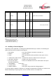


Table Of Contents
- 1 Introduction
- 2 Block Diagram
- 3 Application Interface
- 3.1 Power Supply
- 3.2 Power-up / -down Slew-Rate
- 3.3 Reset
- 3.4 Supply Voltage Monitor
- 3.5 Serial Interface
- 3.6 GPIO Interface
- 3.7 I2C Interface0F
- 3.8 SPI Serial Peripheral Interface1F
- 1.1
- 3.9 Bluetooth Radio Interface
- 3.10 WLAN Coexistence Interface2F
- 3.11 Slow Clock Interface
- 3.12 Test Mode Enable
- 3.13 Pin Strapped System Memory Boot Mode Invocation
- 3.14 Operating in a Power-Switched Environment
- 3.15 Serial Wire Interface
- 4 Module Pins
- 5 Electrical Characteristics
- 6 Mechanical Characteristics
- 1
- 7 Application Diagram
- 8 Approvals/Certifications
- 9 Related Documents
- 10 Packing
- 11 Ordering Information

BlueMod+SR/AI
BlueMod+SR/AP
Hardware Reference
Release r04d01 www.stollmann.de Page 21 of 65
3.13 Pin Strapped System Memory Boot Mode Invocation
Asserting BOOT0 “high” will invoke the system memory bootloader at start-up. This is required for
firmware update. Thus, access to this signal and a means to drive it at high level should be
foreseen by the customer’s hardware. While not in use, this signal can be left open or driven to
logic low level.
To connect to the module during system memory boot mode, an RS232 serial interface has to be
directly linked to the UART-TXD (F-4) and UART_RXD (D-2) pins.
The bootloader is stored in the internal boot ROM memory (system memory) of MCU. It is
programmed during production. Its main task is to upgrade the firmware to the internal Flash
memory. A communication protocol is defined with a specific command set and sequences.
The firmware upgrade will be done by either
- a Stollmann provided firmware update tool. This is a Windows program that contains the
firmware and uses a PC with a serial port for the update
- implementing the system memory boot mode protocol on the host system.
If firmware update shall be performed from a host MCU, signals BOOT0 and EXT-RES# both must
be controlled by that host MCU (GPIO ports). Please note that EXT-RES# must not be driven
directly from a push-pull signal (see chapter 3.3).
3.14 Operating in a Power-Switched Environment
A potential "back feeding" problem may arise, if the module is operated in an environment where
its power supply (VSUP) is switched off by the application. This might be done to save some power
in times Bluetooth is not needed.
As stated in Table 6, the voltage on any I/O pin must not exceed VSUP by more than 0,4V at any
time. Otherwise some current I
INJECT
flows through the internal protection diodes. This may damage
the module.
There is no problem if the application circuit design and programming can assure that all signals
directed towards BlueMod+SR are set to low (U < 0,3V) before and while VSUP is turned off. If this
is not guaranteed, at least a series resistor (about 1k) must be inserted into the signal path. This
does protect the module but obviously cannot prevent from an unwanted, additional current flow in
case of such signal being at high-level. It may be necessary to use driver chips in such
applications, that gate off these signals while VSUP is not present.