
User's Manual


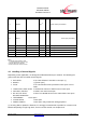


Table Of Contents
- 1 Introduction
- 2 Block Diagram
- 3 Application Interface
- 3.1 Power Supply
- 3.2 Power-up / -down Slew-Rate
- 3.3 Reset
- 3.4 Supply Voltage Monitor
- 3.5 Serial Interface
- 3.6 GPIO Interface
- 3.7 I2C Interface0F
- 3.8 SPI Serial Peripheral Interface1F
- 1.1
- 3.9 Bluetooth Radio Interface
- 3.10 WLAN Coexistence Interface2F
- 3.11 Slow Clock Interface
- 3.12 Test Mode Enable
- 3.13 Pin Strapped System Memory Boot Mode Invocation
- 3.14 Operating in a Power-Switched Environment
- 3.15 Serial Wire Interface
- 4 Module Pins
- 5 Electrical Characteristics
- 6 Mechanical Characteristics
- 1
- 7 Application Diagram
- 8 Approvals/Certifications
- 9 Related Documents
- 10 Packing
- 11 Ordering Information

BlueMod+SR/AI
BlueMod+SR/AP
Hardware Reference
Release r04d01 www.stollmann.de Page 22 of 65
3.15 Serial Wire Interface
The Serial Wire interface SWDIO, SWCLK is normally not used in a customer’s product. It is
reserved for debugging purposes.
Leave SWDIO, SWCLK unconnected. Only if you intend to use it for debugging purposes, make it
available and connect SWDIO via a pullup resistor 100kΩ to VSUP (refer to [1]).
4 Module Pins
4.1 Pin Numbering
F1
E1
D1
C1
B1
A1 A2 A3 A4 A5 A6 A7 A8
F2
E2
D2
C2
B2
F3
E3
D3
C3
B3
F4
E4
D4
C4
B4
F5
E5
D5
C5
B5
F6
E6
D6
C6
B6
F7
E7
D7
C7
B7
F8
E8
D8
C8
B8
Figure 10: BlueMod+SR Pin Numbering (Top View)