
User's Manual
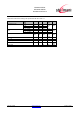

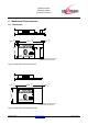


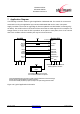
Table Of Contents
- 1 Introduction
- 2 Block Diagram
- 3 Application Interface
- 3.1 Power Supply
- 3.2 Power-up / -down Slew-Rate
- 3.3 Reset
- 3.4 Supply Voltage Monitor
- 3.5 Serial Interface
- 3.6 GPIO Interface
- 3.7 I2C Interface0F
- 3.8 SPI Serial Peripheral Interface1F
- 1.1
- 3.9 Bluetooth Radio Interface
- 3.10 WLAN Coexistence Interface2F
- 3.11 Slow Clock Interface
- 3.12 Test Mode Enable
- 3.13 Pin Strapped System Memory Boot Mode Invocation
- 3.14 Operating in a Power-Switched Environment
- 3.15 Serial Wire Interface
- 4 Module Pins
- 5 Electrical Characteristics
- 6 Mechanical Characteristics
- 1
- 7 Application Diagram
- 8 Approvals/Certifications
- 9 Related Documents
- 10 Packing
- 11 Ordering Information

BlueMod+SR/AI
BlueMod+SR/AP
Hardware Reference
Release r04d01 www.stollmann.de Page 50 of 65
7 Application Diagram
The following schematic shows a typical application of BlueMod+SR. The module is connected to
some MCU running the application layer. MCU and BlueMod+SR use the same 3,3V power
supply. Provisions are made for upgrading the firmware (BOOT0 and EXT-RES# are managed by
the MCU). The serial interface has RTS/CTS flow control but no UICP support in this example. The
Hangup feature to close down the link is provided. As an option to save power, there is an external
slow clock oscillator. All other module pins may be left unconnected.
Host MCU
VDD
GND
+3V3
GPIO (o)
In this example BlueMod+SR is connected to an MCU supporting RTS/CTS flow control and Hangup.
Firmware update is supported (BOOT0, EXT-RES# connected).
The slow clock oscillator (32,768kHz ) is optional; it helps to save power during power down states.
1k
BlueMod+SR/AI
C-1,E-6,F-6
VSUP
GND
B-1
EXT-RES#
BOOT0
GPIO (o)
UART-RXD
UART-TXD
UART-CTS#
UART-RTS#
GPIO[4]/Hangup
TXD (o)
RXD (i)
RTS# (o)
CTS# (i)
GPIO (o)
SLCK
32,768kHz
square
+3V3
The oscillator is optional. Leave A-6 open
or tie to GND if the oscillator is not present.
E-1
D-2
F-4
F-3
D-7
D-4
A-6
all GND pads (14) must be connected.
Blocking capacitors not shown.
pushpull or OD
pushpull
pushpull
Figure 19: Typical Application Schematics