
User's Manual


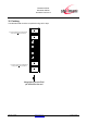


Table Of Contents
- 1 Introduction
- 2 Block Diagram
- 3 Application Interface
- 3.1 Power Supply
- 3.2 Power-up / -down Slew-Rate
- 3.3 Reset
- 3.4 Supply Voltage Monitor
- 3.5 Serial Interface
- 3.6 GPIO Interface
- 3.7 I2C Interface0F
- 3.8 SPI Serial Peripheral Interface1F
- 1.1
- 3.9 Bluetooth Radio Interface
- 3.10 WLAN Coexistence Interface2F
- 3.11 Slow Clock Interface
- 3.12 Test Mode Enable
- 3.13 Pin Strapped System Memory Boot Mode Invocation
- 3.14 Operating in a Power-Switched Environment
- 3.15 Serial Wire Interface
- 4 Module Pins
- 5 Electrical Characteristics
- 6 Mechanical Characteristics
- 1
- 7 Application Diagram
- 8 Approvals/Certifications
- 9 Related Documents
- 10 Packing
- 11 Ordering Information

BlueMod+SR/AI
BlueMod+SR/AP
Hardware Reference
Release r04d01 www.stollmann.de Page 61 of 65
10.1 Tape
The dimensions of the tape are shown in the drawing below (values in mm):
2,0
+0,1
-0,1
10,9
+0,1
-0,1
18,3
+0,1
-0,1
R 0,5
1,75
+0,10
-0,10
24,0
+0,3
-0,3
10x4,0=40,0
+0,2
-0,2
1,5
+0,1
-0,0
12,0
11,5
+0,1
-0,1
0,3
3,0
10.2 Reel
tbd