
User's Manual


UC864-E Hardware User Guide
1vv0300766a Rev.1 - 31/01/08
Reproduction forbidden without Telit Communications S.p.A. written authorization - All Rights Reserved page 40 of 51
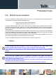
10.4.2 Output lines (speaker)
During designing, remember that while no difference could be if the amplifiers drive an external
amplifier, there are slightly different electrical performances when the load is driven directly from the
internal audio amplifiers, due to differential output voltage.
Line coupling DC
Line type Differential
Output load resistance 32 Ω
Max. Load capacitance 500pF(max)
Differential output impedance 1 Ω (max) @ 1.02KHz
Signal bandwidth 150 - 4000 Hz @ -3 dB
Differential output voltage @ 0dBm0 1.06 V
rms
(typical)
Number of volume steps 10
Volume level step -2dB
Table 3. “Ear_MT” Buffers
Line coupling DC
Line type Differential
Output load resistance 32 Ω
Max. load capacitance 500pF(max)
Differential output resistance 1 Ω (max) @ 1.02KHz
Signal bandwidth 150 - 4000 Hz @ -3 dB
Differential output voltage @ 0dBm0 833mV
rms
(typical)
Number of volume steps 10 (SW)
Volume level step -2dB
Table 4. “Ear_HF” Buffers
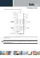
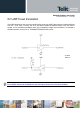
We suggest to drive the load differentially from both receive drivers, thus the output swing is doubled
and the need for the output coupling capacitor is eliminated. However for particular OEM application
needs also a Single Ended circuitry can be implemented, but reducing by four the output power.
The OEM circuitry shall be designed to reduce the common mode noise typically generated on the
ground plane and to get the maximum power output from the device (low traces resistance).
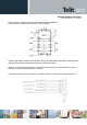
Audio amplifiers could be design in two configurations: balanced (or differential) and unbalanced (or
single-ended).
The differential output power amplifier configuration is also called BTL (bridge-tied load).
In the following a discussion about the use of the two input and output amplifier configurations will be
dealt with.
Also calculation and circuit examples will be exhaustively performed.