
Indoor Fireplace User Manual


10
41DVN / DVSN Direct Vent Gas Fireplace
20009999
FP1024
alternate
remote switch
location
1/27/00 djt
FP1024
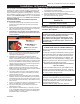
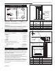
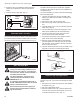
Fig. 8 Alternate switch location.
Alternate Switch Location
The remote switch can be installed on either side of
the access door. Mount the switch to the switch bracket
provided. Screw the bracket on either side of the frame,
line up the screws with the prepunched holes. (Fig. 8)
EB-1 Electrical Box
The fireplace, when installed, must be elec-
trically connected and grounded in accor-
dance with local codes or, in the absence
of local codes, with the current CSA C22.1
Canadian Electrical Code.
For USA installations, follow the local
codes and the national Electrical Code
ANSI/NFPA No. 70.
It is strongly suggested that the wiring of
the EB-1 Electrical Junction Box be carried
out by a licensed electrician.
Ensure that the power to the supply line
has been disconnected before commenc-
ing this procedure.
TPTH
TH
TP
FP1218
Remote switch
wiring
8/02
FP1218
Remote
ON/OFF
Switch
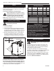
Fig. 7 Remote switch wiring diagram for millivolt models.
The EB-1 electrical junction box has been supplied
standard on all models to allow for easy installation of
an optional fan kit.
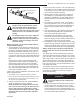
To connect the EB-1 box to the house electrical supply,
follow the steps below.
1. Unscrew the retaining screw from the EB-1 base
plate (Fig. 9) and remove the EB-1 assembly from
the fireplace.
2. Remove the front cover of the EB-1 box.
3. Remove the plug socket assembly from the EB-1
box.
4. Feed the supply line in from the outside through the
cable clamp. (Fig. 9)
5. Connect black wire of the power supply line to the
brass screw (polarized) of the socket assembly.
6. Connect the white wire of the power line to the
chrome screw of the socket assembly.
7. Connect the ground wire of the supply line to the
green screw of the socket assembly.
8. Refit the socket assembly back into the electrical
box and replace the cover plate. Secure the cable
with the clamp on the outside of the unit to prevent
strain on the connections.
9. The EB-1 electrical junction box is now ready to sup-
ply power to the FK12 or FK24 fan kits if fitted.
FP580
Fig. 9 EB-1 receptacle.
FP580
INSTA VENT FREE
EB1 JUNCTION BOX
11/18/97
OUTSIDE
ELECTRICAL BOX
FRONT OF UNIT
INSIDE
FRONT OF UNIT
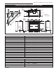
Optional Top Vent Application
The fireplace is shipped as a rear vent unit. If the layout
requires a top vent, convert the unit following the steps
below.
1. Remove the 10 screws securing outer collar adapter
to fireplace. (Fig. 10)
2. Set outer collar adapter aside.
3. Remove insulation from top of unit and discard. Re-
move the four (4) screws securing flue cover to top
of unit and remove flue cover. (Fig. 11)
2. Attach the wire to the ON/OFF switch and install
switch into receptacle box. Attach cover plate to
switch.
3. Connect wiring to gas valve. (Fig. 7)