
Indoor Fireplace User Manual


8
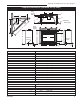
41DVN / DVSN Direct Vent Gas Fireplace
20009999
Hearth
A hearth is not mandatory, but is recommended for
aesthetic purposes. We recommend a noncombustible
hearth which projects out 12” (305 mm) or more from
the front of the fireplace.
Cold climate installation recommendation:
When installing this unit against a non-in-
sulated exterior wall or chase, it is manda-
tory that the outer walls be insulated to
conform to applicable insulation codes.
NOTE: Never allow vapor barrier to contact the outer
casing of this fireplace or venting.
Framing And Finishing
Check fireplace to make sure it is levelled
and properly positioned.
To mount the appliance:
1. Choose the location.
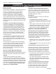
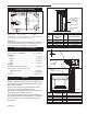
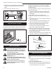
2. This unit comes with four (4) flanges pre-mounted
on both sides of the fireplace to allow two different
drywall thicknesses to be used. Flange “A” is for 1/2”
drywall while flange “B“ is for 5/8” drywall. (Fig. 5)
3. Bend the desired flanges out 90° on both sides of
the fireplace. Slide the fireplace into the framed
opening until the flanges contact the front surfaces
of the framing. Level the unit and secure it firmly in
place.
Final Finishing
Noncombustible materials such as brick or tile can be
extended over the edges of the face of the fireplace.
Do not cover the window frame assembly, any vent,
louvre assembly top or louvre assembly bottom. If
a Trim Kit is to be installed, brick and tile will have to be
installed flush with the side of this appliance.
A
B
FP1539
flange location
12/04
Fig. 5 Drywall flange location.
Flange Location for Desired
Drywall Depth
Screw Drywall
Position Depths
A 1/2” / 13mm
B 5/8” / 16mm
FP1539
Gas Inlet and Manifold Pressures
Natural LP (Propane)
Minimum Inlet Pressure 5.5” w.c. 11.0” w.c.
Maximum Inlet Pressure 14.0” w.c. 14.0” w.c.
Manifold Pressure 3.5” w.c. 10.0” w.c.
High Elevations
Input ratings are shown in BTU per hour and are
certified without deration for elevations up to
4,500 feet (1,370 m) above sea level.
For elevations above 4,500 feet (1,370 m) in USA,
installations must be in accordance with the
current ANSI Z223.1/NFPA 54 and/or local codes
having jurisdiction.
In Canada, please consult provincial and/or local
authorities having jurisdiction for installations at
elevations above 4,500 feet (1,370 m).
Gas Line Installation
When purging gas line the front glass must
be removed.
The gas pipeline can be brought in through the right
side of the appliance. Knockouts are provided at con-
venient locations to allow for the gas pipe installation
and testing of any gas connection.
The gas line connection can be made with properly
tinned 3/8” copper tubing, 1/2” rigid pipe or an approved
flex connector. Since some municipalities have
additional local codes, it is always best to consult your
local authority and the CSA-B149.1 installation codes.
For USA installations consult the current National Fuel
Gas Code, ANSI Z223.1/NFPA 54.
Gas Specifications
Max. Min.
Gas Input Input
Model Fuel Control BTUH BTUH
41DVN Natural Gas Millivolt Hi/Lo 30,000 20,000
41DVP Propane Millivolt Hi/Lo 27,000 19,000
41DVDSN Natural Gas 120 Volt 30,000 --
41DVDSP Propane 120 Volt 27,000 --