
Indoor Fireplace User Manual


9
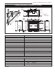
41DVN / DVSN Direct Vent Gas Fireplace
20009999
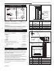
Optional Remote ON/OFF Switch
Installation
Do not wire the remote ON/OFF wall switch
for this gas appliance into a 120v power
supply.
1. Thread wire through the electrical knockout located
on either side of the unit. Take care not to cut the
wire or insulation on metal edges. Ensure the wire is
secured and protected from possible damage. Run
one end of the gas control valve and the other end to
the conveniently located wall switch.
Always check for gas leaks with a mild
soap and water solution applied with a
brush no larger than 1” (25 mm). Never
apply soap and water solution with a spray
bottle. Do not use an open flame for leak
testing.
The fireplace valve must not be subjected
to any test pressures exceeding 1/2 psi.
Isolate or disconnect this or any other gas
appliance control from the gas line when
pressure testing.
When purging gas line, the front window frame as-
sembly must be removed.
1. The gas pipeline can be brought in through the rear
of the fireplace as well as the bottom. Knockouts are
provided on the bottom behind the valve to allow for
the gas pipe installation and testing of any gas con-
nection. It is most convenient to bring the gas line in
from the rear right side of the valve as this allows fan
installation or removal without disconnecting the gas
line.
The gas line connection can be made with prop
-
erly tinned 3/8” copper tubing, 3/8” rigid pipe or an
approved flex connector. Since some municipali-
ties have additional local codes, it is always best to
con- sult your local authority and the National Fuel
Gas Code, ANSI Z223.1/NFPA 54 in the USA or the
CSA-B149.1 installation codes.
*Adhere to the following installation requirements in the
State of Massachusetts:
• The installer must be a licensed plumber or gas fitter.
• Flex connectors must be Massachusetts approved, cannot
exceed 36” (914 mm) in length, must be a minimum 1/2”
dia. and may not penetrate a wall.
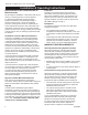
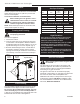
2. The gas control inlet is 3/8” NPT. typical installation
layout for rigid pipe is shown in Figure 8.
NOTE: All models are equipped with a flex tube
with a shut off valve having a 1/2” NPT inlet. The
flex line with shut off is shipped in the control
valve compartment. Using two wrenches, tighten
the flexible tube at the shut off valve and at the
gas control
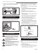
FP297A
INSTA VENT FREE
UVHB26 GAS SUPPLY
7/1/98
1/2” Gas Supply
1/2” NPT x 3/8” Flare Shut-off
Valve
3/8” Flex Line
(from valve)
FP297a
Fig. 6 Typical gas supply installation.
3. When using a flex connector,* use only approved fit-
tings. When a union is installed, provide easy access
in its placement for servicing. Refer to gas specifica-
tion for pressure details and ratings.
4. When a vertical section of gas pipe is required for
the installation, a condensation trap is needed. In
Canada see CSA-B149.1 for code details. See the
National Fuel Gas Code ANSI Z223.1/NFPA 54 in
the USA.
5. For natural gas, a minimum of 3/8” iron pipe with a
gas supply pressure of 4.5” w.c. (from the gas me
-
ter). Consult with local gas utility and ANSI Z223.1/
NFPA 54 if any questions arise concerning pipe
sizes.
6. Turn the gas supply to ‘ON’ and check for leaks. DO
NOT USE OPEN FLAME FOR THIS PURPOSE.
Use an approved leak testing solution.
7. The appliance and its appliance main gas valve
must be disconnected from the gas supply piping
system during any pressure testing of that system at
test pressures in excess of 1/2 psig (3.5kPa).
8. This appliance must be isolated from the gas supply
piping system by closing its equipment shut off valve
during any pressure testing of the gas supply piping
system at test pressures equal to 1/2 psig (3.5KPa).
Always check for gas leaks with a mild soap and
water solution. Do not use an open flame for leak
testing.
The millivolt gas control is equipped with a captured
screw type pressure test point, therefore it is not neces-
sary to provide a 1/8” test point up stream of the control.
When using copper or flex connector use only approved
fittings. Always provide a union when using black iron
pipe so that the gas line can be easily disconnected for
burner or fan servicing . See gas specifications for pres-
sure details and ratings.
The fireplace valve must not be subjected to any test
pressures exceeding 1/2 psi. Isolate or disconnect this
or any other gas appliance control from the gas line
when pressure testing.