
Installation Manual

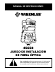


Greenlee Textron / Subsidiary of Textron Inc.
5
4455 Boeing Dr., Rockford, IL 61109-2988 815/397-7070
Fiber Optic Installation Kit
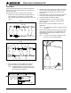
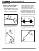
Template
-1" -.5" 0 .5" 1" 1.5" 2"
Glass Fiber
.75"
.5"
Kevlar 1.5"
Buffer
Jacket
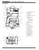
Dust Cap Ferrule Connector
Crimp
Area
Crimp
Ring
Cable Boot
TYPE-I (3mm)
TYPE-II (900µm)
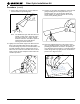
Dust Cap Housing
Ferrule
Assembly
Fiber
Crimp
Area
Crimp
Sleeve
Aramid
Yarn
Buffer Cable
SpringFerruleInner Housing
Jacket
Boot
TYPE-I (3mm)
TYPE-II (900µm)
ST
®
Style
SC Style
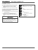
Procedure
These general instructions are for reference purposes.
Contact the connector manufacturer for instructions for
specific connectors.
This procedure is for ST
®
and SC style connectors.
1. Remove the connector from its package. Slide the
strain relief boot, small end first, onto the cable.
Then slide the crimp sleeve, small end first, onto the
cable.
2. Place the cable onto the template and mark the
jacket according to the measurements shown.
Note: Stripping lengths for connectors may vary.
Stripping templates may be obtained from
the connector manufacturer.
3. Starting at the mark closest to the fiber end, remove
the outer jacket using the jacket remover. Use the
scissors to trim the aramid yarn (Kevlar
®
) to the
same mark.
4. At the next mark, cut and remove the outer jacket to
expose the required length of new aramid yarn.
5. Use the template and mark the buffer.
6. In small increments - 5 to 10 mm (1/4" to 3/8") -
remove the buffer and acrylate coating with the
buffer strippers.
7. Place the cable onto the template to check the
dimensions.
Note: For distribution style fiber, mark and remove
the buffer.
8. Using a wipe saturated with alcohol, clean the glass
fiber. Dip the glass portion of the stripped fiber into
the OptiCure™ Primer and set aside to dry for at
least one minute.
Note: You may use the brush to apply the primer.
Be sure to cover all exposed glass.