
Datasheet

Functional Description
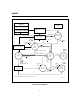
Figure 3 shows a block diagram and Figure 4 shows a
state diagram of the bq2004.
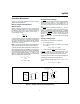
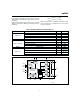
Battery Voltage and Temperature
Measurements
Battery voltage and temperature are monitored for
maximum allowable values. The voltage presented on
the battery sense input, BAT, should represent a
two-cell potential for the battery under charge. A
resistor-dividerratioof:
RB1
RB2
=
N
2
-1
is recommended to maintain the battery voltage within
the valid range, where N is the number of cells, RB1 is
the resistor connected to the positive battery terminal,
and RB2 is the resistor connected to the negative bat
-
tery terminal. See Figure1.
Note: This resistor-divider network input impedance to
end-to-end should be at least 200kΩ and less than 1MΩ.
A ground-referenced negative temperature coefficient ther-
mistor placed in proximity to the battery may be used as a
low-cost temperature-to-voltage transducer. The tempera-
ture sense voltage input at TS is developed using a
resistor-thermistor network between V
CC
and V
SS
. See
Figure 1. Both the BAT and TS inputs are referenced to
SNS, so the signals used inside the IC are:
V
BAT
-V
SNS
=V
CELL
and
V
TS
-V
SNS
=V
TEMP
Discharge-Before-Charge
The DCMD input is used to command discharge-before-
charge via the DIS output. Once activated, DIS be
-
comes active (high) until V
CELL
falls below V
EDV,
at
which time DIS goes low and a new fast charge cycle be
-
gins.
The DCMD
input is internally pulled up to V
CC
(its inac
-
tive state). Leaving the input unconnected, therefore,
results in disabling discharge-before-charge. A negative
going pulse on DCMD
initiates discharge-before-charge
at any time regardless of the current state of the
bq2004. If DCMD
is tied to V
SS
, discharge-before-
charge will be the first step in all newly started charge
cycles.
Starting a Charge Cycle
Anew charge cycle (see Figure 2) is started by:
1. V
CC
rising above 4.5V
2. V
CELL
falling through the maximum cell voltage,
V
MCV
where:
V
MCV
= 0.8 ∗ V
CC
± 30mV
3. Atransition on the INH
input from low to high.
If DCMD
is tied low, a discharge-before-charge is exe-
cuted as the first step of the new charge cycle. Other-
wise, pre-charge qualification testing is the first step.
The battery must be within the configured temperature
and voltage limits before fast charging begins.
The valid battery voltage range is V
EDV
<V
BAT
<V
MCV
where:
V
EDV
= 0.4 ∗ V
CC
± 30mV
3
bq2004
Fg2004a.eps
N
T
C
bq2004
V
CC
PACK +
PACK -
T
S
SNS
RT1
RT2
RB2
RB1
bq2004
Negative Temperature
Coefficient Thermister
PACK+
PACK-
BAT
SNS
Figure 1. Voltage and Temperature Monitoring