
Datasheet

and enforced again on the top-off phase, if selected.
There is no time limit on the trickle-charge phase.
Top-off Charge
An optional top-off charge phase may be selected to
follow fast charge termination for the C/2 through 4C
rates. This phase may be necessary on NiMH or other
battery chemistries that have a tendency to terminate
charge prior to reaching full capacity. With top-off en
-
abled, charging continues at a reduced rate after
fast-charge termination for a period of time equal to
the fast-charge safety time (See Table 1.) During top-
off, the MOD pin is enabled at a duty cycle of 260µsac
-
tive for every 1820µs inactive. This modulation results
in an average rate 1/8th that of the fast charge rate.
Maximum voltage, time, and temperature are the only
termination methods enabled during top-off.
Pulse-Trickle Charge
Pulse-trickle charging follows the fast charge and op
-
tional top-off charge phases to compensate for self-
discharge of the battery while it is idle in the charger.
The configured pulse-trickle rate is also applied in the
charge pending state to raise the voltage of an over-
discharged battery up to the minimum required before
fast charge can begin.
In the pulse-trickle mode, MOD is active for 260µsofa
period specified by the settings of TM1 and TM2. See
Table 1. The resulting trickle-charge rate is C/64 when
top-off is enabled and C/32 when top-off is disabled.
Both pulse trickle and top-off may be disabled by tying
TM1 and TM2 to V
SS
.
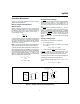
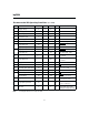
Charge Status Indication
Charge status is indicated by the LED
1
and LED
2
out
-
puts. The state of these outputs in the various charge cy
-
cle phases is given in Table 2 and illustrated in Figure 2.
In all cases, if V
CELL
exceeds the voltage at the MCV
pin, both LED
1
and LED
2
outputs are held low regard
-
less of other conditions. Both can be used to directly
drive an LED.
Charge Current Control
The bq2004 controls charge current through the MOD
output pin. The current control circuitry is designed to
support implementation of a constant-current switching
regulator or to gate an externally regulated current
source.
When used in switch mode configuration, the nominal
regulated current is:
I
REG
= 0.225V/R
SNS
Charge current is monitored at the SNS input by the
voltage drop across a sense resistor, R
SNS
, between the
low side of the battery pack and ground. R
SNS
is sized
to provide the desired fast charge current.
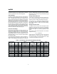
6
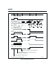
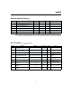
Corresponding
Fast-Charge
Rate TM1 TM2
Typical
Fast-Charge Safety
Time (minutes)
Typical
PVD, -
∆
V Hold-Off
Time (seconds)
Top-Off
Rate
Pulse-
Trickle
Rate
Pulse-
Trickle
Period (Hz)
C/4 Low Low 360 137 Disabled Disabled Disabled
C/2 Float Low 180 820 Disabled C/32 240
1C High Low 90 410 Disabled C/32 120
2C Low Float 45 200 Disabled C/32 60
4C Float Float 23 100 Disabled C/32 30
C/2 High Float 180 820 C/16 C/64 120
1C Low High 90 410 C/8 C/64 60
2C Float High 45 200 C/4 C/64 30
4C High High 23 100 C/2 C/64 15
Note: Typical conditions = 25°C, V
CC
= 5.0V.
Table 1. Fast-Charge Safety Time/Hold-Off/Top-Off Table
bq2004