TA5704EVM 4-Channel Digital Audio Power Amplifier with Hardware Control User's Guide Literature Number: SLOU224 April 2008
SLOU224 – April 2008 Submit Documentation Feedback
Contents Preface ........................................................................................................................................ 5 1 Overview ............................................................................................................................. 7 2 3 1.1 TAS5704EVM Features .................................................................................................. 8 1.2 Basic Tools for Initial Board Power up .......................................
www.ti.com List of Figures 1 2 3 4 5 6 7 2-Channel (BTL) Configuration with External Subwoofer EVM (TAS5601EVM2) .................................. 7 2-Channel (SE) + 1-Channel (BTL) Configuration ...................................................................... 8 4-Channel (SE) Configuration .............................................................................................. 8 Top Composite View of TAS5704EVM .................................................................................
Preface SLOU224 – April 2008 Read This First About This Manual This manual describes the operation of the TAS5704EVM evaluation module from Texas Instruments. How to Use this Manual This document contains the following chapters • Chapter 1 – Overview • Chapter 2 – System Interfaces • Chapter 3 – Jumpers and Control Utilities on TAS5704 • Chapter 4 – TAS5704EVM Layout Information About Cautions and Warnings This manual may contain cautions and warnings. CAUTION This is an example of a caution statement.
Additional Documentation www.ti.com Additional Documentation • General Application Notes EVM Warnings / Restrictions and FCC Warning See the Evaluation Board/Kit Warnings and Restrictions page towards the end of this User's Guide.
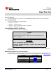
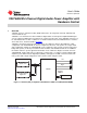
User's Guide SLOU224 – April 2008 TA5704EVM 4-Channel Digital Audio Power Amplifier with Hardware Control 1 Overview TAS5704 customer evaluation module (EVM) demonstrates the integrated circuit (IC) TAS5704 from Texas Instruments (TI). TAS5704 is a 4-channel device with an I2S/RJ/LJ digital audio stream input and amplified PWM signal out. The subwoofer PWM signal is provided to an external class D power stage (TAS5601), which uses a LC demodulation filter to drive a subwoofer.
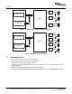
Overview www.ti.com SPDIF/ Optical, Coax LC + Cap Left LC + Cap Right I2S TAS5704 2CH Analog Input from Other Source/ Digital Out Sub LC Figure 2. 2-Channel (SE) + 1-Channel (BTL) Configuration SPDIF/ Optical, Coax LC + Cap LFront LC + Cap RFront LC + Cap LRear LC + Cap RRear I2S TAS5704 2CH Analog Input from Other Source/ Digital Out Figure 3. 4-Channel (SE) Configuration 1.
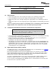
System Interfaces www.ti.com Figure 4. Top Composite View of TAS5704EVM 1.2 Basic Tools for Initial Board Power up • • • • • • 2 Up to 26V, 3A power supply (PVCC) 5V, 500mA power supply (VIN) Banana cables for power supplies and speakers Optical or coaxial cable for SPDIF interface based on signal source Two 8Ω speakers (BTL) or 4Ω speakers (SE).
System Interfaces www.ti.com Table 1. Recommended Power Supplies Description Voltage Limitations (8 Ω load) Current Recommendations System power supply 5V 500 mA Output power stage supply 10 – 26 V 3A (1) (1) 2.2 The rated current correspond to 2 channels at 20W per channel. PSC Connector • • • • Connect the Connect the Connect the PVCC. Connect the PGND. positive node of the 5V (VIN) power supply to the red binding post marked VIN.
Jumpers and Control Utilities www.ti.com 2.5 ADC Interface In the absence of digital signal source ADC (PCM1808) may be used to convert an analog audio signal to digital signal and provide it to TAS5704. DIR9001 still provides clocks to ADC in this process. The frequency of the oscillator selected for DIR 9001determinse the sampling frequency in the absence of digital signal.
Jumpers and Control Utilities 3.4 www.ti.com GAIN Jumpers GAIN0 and GAIN1 jumpers enable the user to change the gain of the device. It is important to assert RESET (S2 labeled MASTER RESET) after each gain change in order for the device to recognize the new gain configuration. The truth table is shown below and also it is marked on the EVM board. However, the gain settings are WRONG on the EVM silkscreen. Refer to Table 3 for the correct gain settings. Table 3. TAS5704 Gain Configuration 3.
Jumpers and Control Utilities www.ti.com Table 6. TAS5704 Output Configuration 3.7 Jumper CFG2 Shunt IN = 0 Jumper CFG1 Shunt IN = 0 0 0 2-Channel BTL Mode (AD Modulation). Connect speakers across OUTA/OUTB and OUTC/OUTD. 0 1 2-Channel BTL Mode (BD Modulation). Connect speakers across OUTA/OUTB and OUTC/OUTD. 1 0 2-Channel SE Mode AND 1-Channel BTL Mode (AD Modulation).
Board Layout, Bill of Material, and Schematics 4 Board Layout, Bill of Material, and Schematics 4.1 TAS5704EVM Board Layout, Top Composite View www.ti.com Figure 5.
Board Layout, Bill of Material, and Schematics www.ti.com 4.2 TAS5704EVM Board Layout, Top Layer View Figure 6.
Board Layout, Bill of Material, and Schematics 4.3 www.ti.com TAS5704EVM Board Layout, Bottom Layer View Figure 7.
Board Layout, Bill of Material, and Schematics www.ti.com 4.4 Bill of Materials Table 7. Bill of Materials for TAS5704EVM Description RefDes QTY MFR MFR:Part No. Vendor Vendor Part No. ALT Part No. TI-SEMICONDUCTORS Modulator/HBRIDGE TQFP64-PAP U1 1 Texas Instruments TAS5704PAP Texas Instruments TAS5704PAP No ALT Part No.
Board Layout, Bill of Material, and Schematics www.ti.com Table 7. Bill of Materials for TAS5704EVM (continued) Description RefDes MFR MFR:Part No. Vendor Vendor Part No. ALT Part No. CAP 1000µF 35V RAD ALUM ELEC FC C51, C52, C62, C75 QTY 4 Panasonic EEU-FC1V102 Digi-Key P10305 No ALT Part No. RES 0.0 Ω 1/16W 5% SMD 0603 R29, R32, R35 3 Panasonic ERJ-3GEY0R00V Digi-Key P0.0GTR P0.0GCT RES 3.3 Ω 1/16W 5% SMD 0603 R11, R13–R15 4 Yageo 9C06031A3R30JLHFT Digi-Key 311-3.
Board Layout, Bill of Material, and Schematics www.ti.com Table 7. Bill of Materials for TAS5704EVM (continued) Description RefDes MFR MFR:Part No. Vendor Vendor Part No. ALT Part No. SHUTDOWN, SUBM, SUBP, VALID QTY 11 Keystone Electronics 5003 Digi-Key 5003K No ALT Part No.
SPDIF RECEIVER ENGINEERING EVALUATION ONLY SPDIF LOCK U2 SPDIF FORMAT RCA INPUT DATA FORMAT FMT1 FMT0 16Bit/MSB/RJ 24Bit/MSB/RJ 24Bit/MSB/LJ 24Bit/MSB/I2S OPTO INPUT L L H H L H L H SHUNTS IN = 0 SHUNTS OUT = 1 JUMPER NOTES 1-2: SPDIF CLOCKS/DATA 2-3: CLOCKS/DATA = PSIA (MCLK) DIR9001PW TO TAS5704 (SDATA) JP1 IN: SCKO = 512 Fs JP1 OUT: SCKO = 256 Fs (DEFAULT) (SCLK) (LRCLK) SPDIF INPUT SELECT JUMPER NOTES 1-2: OPTO INPUT 2-3: COAX INPUT 1-2: SPDIF CLOCKS/DATA (DEFAULT) 2-3: CLOCKS/DATA =
ANALOG TO DIGITAL CONVERTER ENGINEERING EVALUATION ONLY ANALOG INPUTS ADC SDIN CONFIGURATOR JP16 NOTE 1-2: SDIN2 = ADC (DEFAULT) 2-3: SDIN2 = SPDIF/PSIA FROM SPDIF TO TAS5704 PCM1808PW JP15 NOTE 3.3V DECOUPLING 5V DECOUPLING 1-2: SDIN1 = SDIN2 2-3: SDIN1 = SPDIF/PSIA (DEFAULT) TI CX PROJECT: TAS5704 Design Team: RYAN KEHR Mod: NC Schematic Rev: NC Save Date: JULY 10, 2007 Filename: TAS5704EVM.
TAS5704 I/O ENGINEERING EVALUATION ONLY 3.
POWER SUPPLIES ENGINEERING EVALUATION ONLY TO SUBWOOFER DAUGHTERCARD HIGH VOLTAGE POWER INPUTS EMI SNUBBERS TO TAS5704 PVCC = 10-26V TO SUBWOOFER DAUGHTERCARD TO TAS5704 TO SPDIF TO ADC LOW VOLTAGE POWER INPUTS 3.3V@1A SUBWOOFER CONNECTOR FROM P.S.
REVISION CHANGES REVISION NC DESCRIPTION PRE-RELEASE ENGINEERING EVALUATION ONLY DATE 10JUL2007 APPROVAL RK TI CX PROJECT: TAS5704 EVALUTION MODULE Design Team: RYAN KEHR Mod: NC PCB Rev: NC Sheet 5 of 6 Schematic Rev: NC Save Date: JULY 10, 2007 Print Date Tue Jul 10, 2007 Filename: TAS5704EVM.
TEXAS INSTRUMENTS DISCLAIMER ENGINEERING EVALUATION ONLY DISCLAIMER The information and materials ("Materials") provided here are provided by Texas Instruments Incorporated ("TI") as a service to its customers and/or suppliers, and may be used for informational purposes only, and only subject to the following terms. By downloading or viewing these Materials, you are signifying your assent to these terms. 1.
EVALUATION BOARD/KIT IMPORTANT NOTICE Texas Instruments (TI) provides the enclosed product(s) under the following conditions: This evaluation board/kit is intended for use for ENGINEERING DEVELOPMENT, DEMONSTRATION, OR EVALUATION PURPOSES ONLY and is not considered by TI to be a finished end-product fit for general consumer use. Persons handling the product(s) must have electronics training and observe good engineering practice standards.
IMPORTANT NOTICE Texas Instruments Incorporated and its subsidiaries (TI) reserve the right to make corrections, modifications, enhancements, improvements, and other changes to its products and services at any time and to discontinue any product or service without notice. Customers should obtain the latest relevant information before placing orders and should verify that such information is current and complete.