
Ethernet Media Access Controller (EMAC)/ Management Data Input/Output (MDIO) Module User's Guide


www.ti.com
1.4 Industry Standard(s) Compliance Statement
2 Architecture
2.1 Clock Control
2.1.1 MII Clocking
2.1.2 GMII Clocking
Architecture
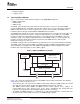
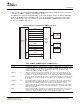
The EMAC and MDIO interrupts are combined within the control module, so only the control module
interrupt needs to be monitored by the application software or device driver. The EMAC control module
combines the EMAC and MDIO interrupts and generates 4 separate interrupts to the ARM through the
ARM interrupt controller. See Section 2.16.4 for details of interrupt multiplex logic of the EMAC control
module.
The EMAC peripheral conforms to the IEEE 802.3 standard, describing the Carrier Sense Multiple Access
with Collision Detection (CSMA/CD) Access Method and Physical Layer specifications. The IEEE 802.3
standard has also been adopted by ISO/IEC and re-designated as ISO/IEC 8802-3:2000(E).
In difference from this standard, the EMAC peripheral does not use the Transmit Coding Error signal
MTXER. Instead of driving the error pin when an underflow condition occurs on a transmitted frame, the
EMAC intentionally generates an incorrect checksum by inverting the frame CRC, so that the transmitted
frame is detected as an error by the network.
This section discusses the architecture and basic function of the EMAC/MDIO module.
The frequencies for the transmit and receive clocks are fixed by the IEEE 802.3 specification as:
• 2.5 MHZ at 10 Mbps
• 25 MHZ at 100 Mbps
• 125 MHZ at 1000 Mbps
All EMAC logic is clocked synchronously with the PLL peripheral clock. The MDIO clock can be controlled
through the application software, by programming the divide-down factor in the MDIO control register
(CONTROL).
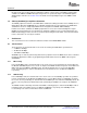
In the 10/100 Mbps mode, the transmit and receive clock sources are provided from an external PHY via
the MTCLK and MRCLK pins. These clocks are inputs to the EMAC module and operate at 2.5 MHZ in 10
Mbps mode and at 25 MHZ in 100 Mbps mode. The MII clocking interface is not used in 1000 Mbps
mode. For timing purposes, data is transmitted and received with reference to MTCLK and MRCLK,
respectively.
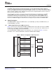
In the 1000 Mbps mode, the transmit and receive clock sources for 10/100 Mbps operation are provided
from an external PHY via the MTCLK and MRCLK pins, as in the MII clocking. For 1000 Mbps operation,
the receive clock is provided by an external PHY via the MRCLK pin. For transmit in 1000 Mbps mode, the
clock is sourced synchronous with the data and is provided by the EMAC to be output on the GMTCLK
pin.
The EMAC module is internally clocked at 148.5 MHZ. For timing purposes, data in 10/100 Mbps mode is
transmitted and received with reference to MTCLK and MRCLK, respectively. For 1000 Mbps mode,
receive timing is the same, but transmit is relative to GMTCLK.
Ethernet Media Access Controller (EMAC)/Management Data Input/Output (MDIO)14 SPRUEQ6 – December 2007
Submit Documentation Feedback