
user manual


SERIES 525 RAINFALL SENSORS
DESCRIPTION
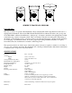
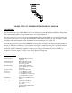
The sensor consists of a gold anodized aluminum collector funnel with a knife-edge that diverts the water to a
tipping bucket mechanism. The models TR-525I and TR-525USW are calibrated in inches (.01” per tip) and
model TR-525M is calibrated in millimeters (.1mm per tip). A magnet is attached to the tipping bucket, which,
as the bucket tips, actuates a magnetic switch. Thus, a momentary switch closure takes place with each tip of
the bucket. Connecting the sensor to an event counter on an electronic datalogger or display module will allow
record keeping of accumulated rainfall. If an analog signal representing rainfall accumulation is required,
Texas Electronics, Inc. manufactures a suitable conditioning circuit.
The spent water drains out of the bottom of the housing; hence, the sensor requires no attention or servicing of
any sort. It is completely automatic. The aluminum sensor housing is finished with a white baked enamel paint
to withstand years of exposure to the environment.
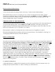
SPECIFICATIONS
Resolution: 0.01” or 0.1 mm
Accuracy:
English
Metric
1.0% at 1”/hr or less
1.0% at 10 mm/hr or less
Average Switch Closure Time: 135 ms
Maximum Bounce Settling Time: 0.75 ms
Maximum Switch Rating: 30 VDC @ 2 A, 115 VAC @ 1 A
Temperature Limits: +32°F to +125°F
Humidity Limits: 0 to 100%
Height: 10.125”
Weight: 2.5 pounds
Receiving Orifice Diameter:
6.060” (English)
9.664” (Metric)
8.000” USW (English)
Cable: 25 feet, 2-conductor
Installation: Consists of attaching the three sensor support legs to a firm
platform or securing the side bracket to a stable vertical structure
such as the lower end of weather station mast. Sensor cable is then
connected to monitoring equipment.
Maintenance:
Occasional cleaning of debris from filter screen may be required.
Warranty: Three Years