
User guide

F, Jumper Locations:
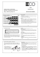
D, Setting Temperature:
- Adjust the temperature to your chosen set-point using the or
buttons.
- Ambient room temperature display will resume after 8 seconds and the
icon will disappear.
E, Jumper Selection:
Delay / No Delay Jumper:
Heater Cooler
No Delay 10sec 4mins
Delay 4mins 4mins
Choose the delay option if compressor heat is connected.
Heater/Cooler Jumper:
Select the heater option (default) when a heater is connected to the
receiver. Select the Cooler option when using the ET3 for a cooling
application, fan cooling etc. Press “reset” (RST) after modifying jumper
selections.
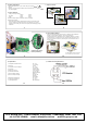
G, Comms Address Setting:
Inside the transmitter and receiver there is a bank of 9 dip switches for
setting a unique address (pairing). The receiver will ignore
communications from transmitters set to a different address. To access
the dip switches it is necessary to open the thermostat and remove the
front cover from the receiver by removing the two crosshead screws on
the rear cover.
7
8
9 10
Transmitter dip switches
Receiver
dip switches
The dip switches on both units must
be set identically to communicate.
H, Specification:
1, Temperature Measurement: 0
0
C - 4
0
C
(0.1
0
C/step)
2, Accuracy: ± 0.5
0
C
3, Temperature Control Range: 5
0
C - 35
0
C
(0.5
0
C/step)
4, Terminals: 2.5mm
2
Cable
5, Electronic Control: Type 2.B action
6, Transmitter Batteries: 2 x 1.5V AAA
Alkaline batteries
7, Receiver Input Voltage: 240V AC
8, Receiver Output Voltage: 24..240V AC
50/60Hz
10(3)A Max
9, Operating Temperature: 0
0
C - 50
0
C
10, Storage Temperature: 0
0
C - 60
0
C
11, Sensing Element: NTC Thermistor
11 12
I, Terminal Connecting Block Label:
1
2
3
Default jumper setting:
No Delay & Heating
TFC Group LLP, Tower House, Vale Rise, Tonbridge, Kent TN9 1TB
tel: 01732 351680 email: sales@tfc.uk.com web:tfc-group.co.uk