Cinterion® ALAS66A Hardware Interface Overview Version: DocId: 01.000a ALAS66A_HIO_v01.000a GEMALTO.
Cinterion® ALAS66A Hardware Interface Overview Page 2 of 51 2 Document Name: Cinterion® ALAS66A Hardware Interface Overview Version: 01.000a Date: 2019-02-26 DocId: ALAS66A_HIO_v01.000a Status: Confidential / Released GENERAL NOTE THE USE OF THE PRODUCT INCLUDING THE SOFTWARE AND DOCUMENTATION (THE "PRODUCT") IS SUBJECT TO THE RELEASE NOTE PROVIDED TOGETHER WITH PRODUCT. IN ANY EVENT THE PROVISIONS OF THE RELEASE NOTE SHALL PREVAIL. THIS DOCUMENT CONTAINS INFORMATION ON GEMALTO M2M PRODUCTS.
Cinterion® ALAS66A Hardware Interface Overview Page 3 of 51 Contents 51 Contents 1 Introduction ................................................................................................................. 6 1.1 Product Variants ................................................................................................ 6 1.2 Key Features at a Glance .................................................................................. 7 1.2.1 Supported Frequency Bands ..............................
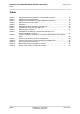
Cinterion® ALAS66A Hardware Interface Overview Page 4 of 51 Tables 51 Tables Table 1: Table 2: Table 3: Table 4: Table 5: Table 6: Table 7: Table 8: Table 9: Table 10: Table 11: Table 12: Table 13: Table 14: Table 15: Supported frequency bands for each ALAS66A variant................................. Supported CA configurations ......................................................................... Signals of the SIM interface (SMT application interface) ...............................
Cinterion® ALAS66A Hardware Interface Overview Page 5 of 51 Figures 51 Figures Figure 1: Figure 2: Figure 3: Figure 4: Figure 5: Figure 6: Figure 7: Figure 8: Figure 9: Figure 10: Figure 11: Figure 12: Figure 13: Figure 14: Figure 15: Figure 16: ALAS66A system overview ............................................................................ USB circuit ..................................................................................................... Serial interface ASC0.......................
Cinterion® ALAS66A Hardware Interface Overview Page 6 of 51 1 Introduction 16 1 Introduction This document1 describes the hardware of the Cinterion® ALAS66A products listed in Section 1.1. It helps you quickly retrieve interface specifications, electrical and mechanical details and information on the requirements to be considered for integrating further components. 1.
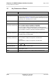
Cinterion® ALAS66A Hardware Interface Overview Page 7 of 51 1.2 Key Features at a Glance 16 1.2 Key Features at a Glance Feature Implementation General Frequency bands Note: Not all of the frequency bands (and 3GPP technologies) mentioned throughout this document are supported by every ALAS66A products variant. Please refer to Section 1.2.1 for an overview of the frequency bands supported by each ALAS66A product variant.
Cinterion® ALAS66A Hardware Interface Overview Page 8 of 51 1.
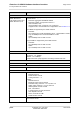
Cinterion® ALAS66A Hardware Interface Overview Page 9 of 51 1.2 Key Features at a Glance 16 Feature Implementation Software Embedded Linux platform Embedded Linux with API (ARC, RIL). Memory space available for Linux applications is 4GB in the flash file system, and 2GB RAM. SIM Application Toolkit SAT Release 99, letter classes b, c, e with BIP and RunAT support Firmware update Linux controlled firmware update.
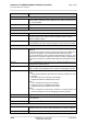
Cinterion® ALAS66A Hardware Interface Overview Page 10 of 51 1.2 Key Features at a Glance 16 Feature Implementation Special Features Antenna SAIC (Single Antenna Interference Cancellation) / DARP (Downlink Advanced Receiver Performance) Rx Diversity (receiver type 3i - 64-QAM) / MIMO HORxD (Higher Order Receive Diversity) with up to 4 antennas GPIO Linux controlled: 18 I/O pins of the application interface programmable as GPIO.
Cinterion® ALAS66A Hardware Interface Overview Page 11 of 51 1.2 Key Features at a Glance 16 1.2.1 Supported Frequency Bands The following table lists the supported frequency bands for each of the ALAS66A product variants mentioned in Section 1.1.
Cinterion® ALAS66A Hardware Interface Overview Page 12 of 51 1.2 Key Features at a Glance 16 Table 1: Supported frequency bands for each ALAS66A variant Band -W -CN -E -US -J Bd.29 (700MHz) x Bd.30 (2300MHz)1 x x Bd.32 (1500MHz) x Bd.66 (1700MHz)2 -K x x x x x x x LTE-TDD Bd.34 (2000MHz) x x Bd.38 (2600MHz) x x Bd.39 (1900MHz) x x x x x x x x x x x x Bd.
Cinterion® ALAS66A Hardware Interface Overview Page 13 of 51 1.2 Key Features at a Glance 16 Table 2: Supported CA configurations Downlink CA Uplink CA Bandwidth combination set Product variants (ALAS66A-...
Cinterion® ALAS66A Hardware Interface Overview Page 14 of 51 1.2 Key Features at a Glance 16 Table 2: Supported CA configurations Downlink CA Uplink CA Bandwidth combination set Product variants (ALAS66A-...
Cinterion® ALAS66A Hardware Interface Overview Page 15 of 51 1.2 Key Features at a Glance 16 Table 2: Supported CA configurations Downlink CA Uplink CA Bandwidth combination set Product variants (ALAS66A-...
Cinterion® ALAS66A Hardware Interface Overview Page 16 of 51 1.3 System Overview 16 1.
Cinterion® ALAS66A Hardware Interface Overview Page 17 of 51 2 Interface Characteristics 33 2 Interface Characteristics ALAS66A is equipped with an SMT application interface that connects to the external application. The SMT application interface incorporates the various application interfaces as well as the RF antenna interface. 2.1 Application Interface 2.1.1 USB Interface ALAS66A supports a USB 3.0 Super Speed (5Gbps) device interface, and alternatively a USB 2.
Cinterion® ALAS66A Hardware Interface Overview Page 18 of 51 2.1 Application Interface 33 2.1.2 Serial Interface ASC0 ALAS66A offers a 4-wire (8-wire prepared) (plus GND) unbalanced, asynchronous interface ASC0 conforming to ITU-T V.24 protocol DCE signaling. The electrical characteristics do not comply with ITU-T V.28. The significant levels are 0V (for low data bit or active state) and 1.8V (for high data bit or inactive state). ALAS66A is designed for use as a DCE.
Cinterion® ALAS66A Hardware Interface Overview Page 19 of 51 2.1 Application Interface 33 2.1.3 Serial Interface ASC1 Four ALAS66A lines can be configured as ASC1 interface signals to provide a 4-wire unbalanced, asynchronous interface ASC1 conforming to ITU-T V.24 protocol DCE signaling. The electrical characteristics do not comply with ITU-T V.28. The significant levels are 0V (for low data bit or active state) and 1.8V (for high data bit or inactive state). ALAS66A is designed for use as a DCE.
Cinterion® ALAS66A Hardware Interface Overview Page 20 of 51 2.1 Application Interface 33 2.1.4 I2C Interface ALAS66A provides two I2C interfaces. I2C is a serial, 8-bit oriented data transfer bus for bit rates up to 400kbps in Fast mode. It consists of two lines, the serial data line I2CDAT and the serial clock line I2CCLK. The module acts as a single master device, e.g. the clock I2CCLK is driven by the module. I2CDAT is a bi-directional line.
Cinterion® ALAS66A Hardware Interface Overview Page 21 of 51 2.1 Application Interface 33 2.1.5 UICC/SIM/USIM Interface ALAS66A has a UICC/SIM/USIM interface compatible with the 3GPP 31.102 and ETSI 102 221. It is wired to the host interface in order to be connected to an external SIM card holder. Five pads on the SMT application interface are reserved for the SIM interface. The UICC/SIM/USIM interface supports 2.85V and 1.8V SIM cards.
Cinterion® ALAS66A Hardware Interface Overview Page 22 of 51 2.1 Application Interface 33 open: Card removed closed: Card inserted Module SMT application interface CCIN CCRST 1n SIM / UICC CCCLK GND CCIO CCVCC 220n Figure 6: First UICC/SIM/USIM interface The total cable length between the SMT application interface pads on ALAS66A and the pads of the external SIM card holder must not exceed 100mm in order to meet the specifications of 3GPP TS 51.
Cinterion® ALAS66A Hardware Interface Overview Page 23 of 51 2.1 Application Interface 33 2.1.6 Digital Audio Interface ALAS66A supports one digital audio interface that can be employed as inter IC sound (I2S) interface. 2.1.6.1 Inter IC Sound Interface (I2S) The I2S Interface is a standardized bidirectional I2S ("Inter-IC Sound Interface") based digital audio interface for transmission of mono voice signals for telephony services.
Cinterion® ALAS66A Hardware Interface Overview Page 24 of 51 2.2 GSM/UMTS/LTE Antenna Interface 33 2.2 GSM/UMTS/LTE Antenna Interface The ALAS66A GSM/UMTS/LTE antenna interface comprises two GSM/UMTS/LTE main antennas as well as two UMTS/LTE Rx diversity/MIMO antennas to improve signal reliability and quality1. The interface has an impedance of 50. ALAS66A is capable of sustaining a total mismatch at the antenna interface without any damage, even when transmitting at maximum RF power.
Cinterion® ALAS66A Hardware Interface Overview Page 25 of 51 2.2 GSM/UMTS/LTE Antenna Interface 33 2.2.1 Antenna Installation The antennas are connected by soldering the antenna pads (ANT_TRX1, ANT_TRX2, ANT_RX3, ANT_RX4; ANT_GNSS) and their neighboring ground pads directly to the application’s PCB. The distance between the antenna pads and their neighboring GND pads has been optimized for best possible impedance.
Cinterion® ALAS66A Hardware Interface Overview Page 26 of 51 2.2 GSM/UMTS/LTE Antenna Interface 33 2.2.2 2.2.2.1 RF Line Routing Design Line Arrangement Instructions Several dedicated tools are available to calculate line arrangements for specific applications and PCB materials - for example from http://www.polarinstruments.com/ (commercial software) or from http://web.awrcorp.com/Usa/Products/Optional-Products/TX-Line/ (free software).
Cinterion® ALAS66A Hardware Interface Overview Page 27 of 51 2.2 GSM/UMTS/LTE Antenna Interface 33 Micro-Stripline This section gives two line arrangement examples for micro-stripline. Figure 8: Micro-Stripline line arrangement samples ALAS66A_HIO_v01.
Cinterion® ALAS66A Hardware Interface Overview Page 28 of 51 2.2 GSM/UMTS/LTE Antenna Interface 33 2.2.2.2 Routing Examples Interface to RF Connector Figure 9 and Figure 10 show a sample connection of a module‘s antenna pad at the bottom layer of the module PCB with an application PCB‘s coaxial antenna connector. Line impedance depends on line width, but also on other PCB characteristics like dielectric, height and layer gap. The sample stripline width of 0.50mm/0.75mm and the spaces of 0.35mm/0.
Cinterion® ALAS66A Hardware Interface Overview Page 29 of 51 2.3 GNSS Antenna Interface 33 2.3 GNSS Antenna Interface In addition to the RF antenna interface ALAS66A also has a GNSS antenna interface. The GNSS pad’s shape is the same as for the RF antenna interface (see Section 2.2.1). It is possible to connect active or passive GNSS antennas. In either case they must have 50 impedance. The simultaneous operation of GSM/UMTS/LTE and GNSS is implemented.
Cinterion® ALAS66A Hardware Interface Overview Page 30 of 51 2.3 GNSS Antenna Interface 33 Figure 12 shows a sample circuit realizing ESD protection for a passive GNSS antenna. Connecting the input ANT_GNSS_DC to GND prevents ESD from coupling into the module. Module SMT interface GNSS _EN 100nF Not used ANT_GNSS _DC (Optional) 0R ESD protection Passive GNSS antenna 10nH ANT_GNSS To GNSS receiver Figure 12: ESD protection for passive GNSS antenna ALAS66A_HIO_v01.
Cinterion® ALAS66A Hardware Interface Overview Page 31 of 51 2.4 Sample Application 33 2.4 Sample Application Figure 13 shows a typical example of how to integrate an ALAS66A module with an application. The PWR_IND line is an open collector that needs an external pull-up resistor which connects to the voltage supply VCC µC of the microcontroller. Low state of the open collector pulls the PWR_IND signal low and indicates that the ALAS66A module is active, high level notifies the Power Down mode.
Cinterion® ALAS66A Hardware Interface Overview Page 32 of 51 2.4 Sample Application 33 GSM/UMTS/LTE IGT GND ANT_TRX1 47k GND GSM/UMTS/LTE GND EMERG _OFF ANT_TRX2 GND 47k UMTS/LTE GND ANT_RX3 GND 100k UMTS/LTE VCC µC GND PWR_IND ANT_RX4 GND GNSS GND ANT_GNSS VDD (1.8V) VEXT (1.8V) VCC µC Module OE V CCA 4 VCCB Level Controller GND PCM interface lines 4 PCM2_... 47µF Ultra low ESR BATT+ 2 Rechargeable Lithium battery BATT+_RF 2 + Serial interface ASC0 8 RXD0, TXD0, ...
Cinterion® ALAS66A Hardware Interface Overview Page 33 of 51 3 GNSS Interface 33 3 GNSS Interface ALAS66A integrates a GNSS receiver that offers the full performance of GPS/GLONASS technology. The GNSS receiver is able to continuously track all satellites in view, thus providing accurate satellite position data. The integrated GNSS receiver supports the NMEA protocol via USB or ASC0 interface.
Cinterion® ALAS66A Hardware Interface Overview Page 34 of 51 4 Mechanical Dimensions and Mounting 35 4 Mechanical Dimensions and Mounting 4.1 Mechanical Dimensions of ALAS66A Figure 14 shows a 3D view1 of ALAS66A and provides an overview of the board's mechanical dimensions2. For further details see Figure 15. Length: 48mm Width: 36mm Height: 3mm Top view Bottom view Figure 14: ALAS66A – top and bottom view 1. The coloring of the 3D view does not reflect the module’s real color. 2.
Cinterion® ALAS66A Hardware Interface Overview Page 35 of 51 4.
Cinterion® ALAS66A Hardware Interface Overview Page 36 of 51 5 Regulatory and Type Approval Information 43 5 Regulatory and Type Approval Information 5.1 Directives and Standards ALAS66A has been designed to comply with the directives and standards listed below.
Cinterion® ALAS66A Hardware Interface Overview Page 37 of 51 5.1 Directives and Standards 43 Table 7: Standards of European type approval ETSI EN 301 489-01 V2.1.1 Electromagnetic Compatibility (EMC) standard for radio equipment and services; Part 1: Common technical requirements; Harmonized Standard covering the essential requirements of article 3.
Cinterion® ALAS66A Hardware Interface Overview Page 38 of 51 5.1 Directives and Standards 43 Table 10: Toxic or hazardous substances or elements with defined concentration limits ALAS66A_HIO_v01.
Cinterion® ALAS66A Hardware Interface Overview Page 39 of 51 5.2 SAR requirements specific to portable mobiles 43 5.2 SAR requirements specific to portable mobiles Mobile phones, PDAs or other portable transmitters and receivers incorporating a GSM module must be in accordance with the guidelines for human exposure to radio frequency energy.
Cinterion® ALAS66A Hardware Interface Overview Page 40 of 51 5.3 Reference Equipment for Type Approval 43 5.3 Reference Equipment for Type Approval The Gemalto M2M general reference setup submitted to type approve ALAS66A is shown in the figure below: Figure 16 illustrates the setup for general tests and evaluation purposes. The evaluation module can be plugged directly onto an Audio Adapter. The GSM/UMTS/LTE/ GNSS test equipment is still connected via SMA connectors on the evaluation module.
Cinterion® ALAS66A Hardware Interface Overview Page 41 of 51 5.4 Compliance with FCC and ISED Rules and Regulations 43 5.4 Compliance with FCC and ISED Rules and Regulations The Equipment Authorization Certification for the Gemalto M2M modules reference application described in Section 5.
Cinterion® ALAS66A Hardware Interface Overview Page 42 of 51 5.4 Compliance with FCC and ISED Rules and Regulations 43 Table 12: Antenna gain limits for FCC and ISED for ALAS66A-US Maximum gain in operating band FCC limit ISED limit Unit Band 7 (LTE-FDD) 6.5 6.5 dBi Band 12 (LTE-FDD) 9.2 5.9 dBi Band 13 (LTE-FDD) 8.7 5.6 dBi Band 66(LTE-FDD) 6.4 6.
Cinterion® ALAS66A Hardware Interface Overview Page 43 of 51 5.4 Compliance with FCC and ISED Rules and Regulations 43 If Canadian approval is requested for devices incorporating ALAS66A modules the above note will have to be provided in the English and French language in the final user documentation. Manufacturers/OEM Integrators must ensure that the final user documentation does not contain any information on how to install or remove the module from the final product.
Cinterion® ALAS66A Hardware Interface Overview Page 44 of 51 6 Document Information 48 6 Document Information 6.1 Revision History Preceding document: "Cinterion® ALAS66A Hardware Interface Overview" v00.001 New document: "Cinterion® ALAS66A Hardware Interface Overview" v01.000a Chapter What is new 1.2.1 Revised support for LTE-FDD Band 41. Added LTE-FDD Band 30. Added note for LTE-FDD Band 66. 1.2.2 Added note that carrier aggregation is planned, and will be supported in a future version. 4.
Cinterion® ALAS66A Hardware Interface Overview Page 45 of 51 6.2 Related Documents 48 6.2 [1] [2] [3] [4] Related Documents ALAS66A Release Note Application Note 48: SMT Module Integration Universal Serial Bus Specification Revision 3.0 Universal Serial Bus Specification Revision 2.0 6.
Cinterion® ALAS66A Hardware Interface Overview Page 46 of 51 6.
Cinterion® ALAS66A Hardware Interface Overview Page 47 of 51 6.
Cinterion® ALAS66A Hardware Interface Overview Page 48 of 51 6.4 Safety Precaution Notes 48 6.4 Safety Precaution Notes The following safety precautions must be observed during all phases of the operation, usage, service or repair of any cellular terminal or mobile incorporating ALAS66A. Manufacturers of the cellular terminal are advised to convey the following safety information to users and operating personnel and to incorporate these guidelines into all manuals supplied with the product.
Cinterion® ALAS66A Hardware Interface Overview Page 49 of 51 7 Appendix 50 7 Appendix 7.
Cinterion® ALAS66A Hardware Interface Overview Page 50 of 51 7.1 List of Parts and Accessories 50 Table 14: Molex sales contacts (subject to change) Molex For further information please click: http://www.molex.com Molex Deutschland GmbH Otto-Hahn-Str. 1b 69190 Walldorf Germany Phone: +49-6227-3091-0 Fax: +49-6227-3091-8100 Email: mxgermany@molex.com American Headquarters Lisle, Illinois 60532 U.S.A.
About Gemalto Since 1996, Gemalto has been pioneering groundbreaking M2M and IoT products that keep our customers on the leading edge of innovation. We work closely with global mobile network operators to ensure that Cinterion® modules evolve in sync with wireless networks, providing a seamless migration path to protect your IoT technology investment.