
Specification Sheet


These warranties give you specific legal rights and you may have other rights that vary from state to state. Limited warranty from date of purchase. For complete warranty details, refer to your
Use & Care manual, or ask your dealer.
Specifications are for planning purposes only. Refer to installation instructions and consult your countertop supplier prior to making counter opening. Consult with a heating and ventilation
engineer for your specific ventilation requirements. For the most detailed information, refer to installation instructions accompanying product or write to Thermador indicating the model
number. Specifications are correct at time of printing. Thermador reserves the right to change product specifications or design without notice. Some models are certified for use in Canada.
Thermador is not responsible for products that are transported from the U.S. for use in Canada.
1 800 735 4328 | USA THERMADOR.COM | CANADA THERMADOR.CA | ©2022 BSH HOME APPLIANCES CORPORATION. ALL RIGHTS RESERVED.
2 / 22
Page 13 of 13
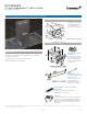
APPLICATION
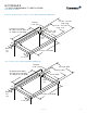
- Allows for non-ducted downdraft installation by eliminating the need
to exhaust to the exterior of the home*
- Recirculation module and metal grill vent plate placement can be
rotated for exible exhaust placement
- Elbow and ductwork are not included
- Use with induction/electric cooktops only
FLEXIBLE BLOWER INSTALLATION – RECIRCULATION EXAMPLE
UCVM36XS
37-INCH DOWNDRAFT VENTILATION
MASTERPIECE
®
SERIES
Page 5
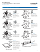
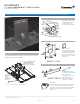
INSTALL THE
RECIRCULATION BOX
1. Cut opening in cabinet base.
• Size: 14 1/2” (368) x 15” (380)
• Orientation depends upon direction of exhaust.
• Double-check that blower outlet and recirculation box inlet will align.
2. Temporarily place recirculation box into opening in cabinet base.
• Rotate back of box up slightly and insert exhaust end down into opening.
• Mark location of exhaust opening in toe space, rear, or side of cabinet.
3. Remove recirculation box from opening.
4. Cut exhaust opening.
• Size: 3 1/2” (89) x 14 1/4” (362)
• This opening will be covered with decorative grille.
5. Replace recirculation box into opening in cabinet base.
• If necessary, attach a length 3 1/4” (83) x 14” (356) duct extension (not
included) to extend from recirculation box outlet to decorative grille
location.
• Seal the duct connection(s) with aluminum tape to make them secure and
air tight. Do not use duct tape.
• Use 6 - #10 x .625” screws to secure recirculation box to cabinet base.
6. Install blower.
• See blower instructions.
• Use 8” (203) round duct to connect blower exhaust to recirculation box
inlet
• Seal the duct connections with aluminum tape to make them secure and
air tight. Do not use duct tape.
• Drill 1/8” (3) pilot holes through top of recirculation box and attach legs
to recirculation box with 4 - #8 x .375” screws.
7. Install decorative grille.
• Use screws provided.
8.
•
•
•
CUSTOM-MADE
DECORATIVE GRILLE
You can make your own decorative grille. Use the decorative grille in
this kit as a template for the overall size and mounting hole locations.
The grille opening pattern is up to you.
2
min.
FILTER REPLACEMENT
6 months. However, this may vary, depending upon the type and
amount of cooking you do. Call customer service or your local
ALIGN BLOWER
OUTLET WITH
RECIRCULATION
BOX INLET
METAL 8” ROUND DUCT
(per local codes)
EXHAUST THROUGH
CABINET FRONT (TOE KICK)
BLOWER
EXHAUST THROUGH
CABINET SIDE
EXHAUST THROUGH
CABINET BACK
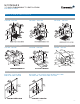
Blower mounted
to downdraft using
mounting legs.
BLOWER
Blower mounted to
framing in remote
location - using
mounting brackets.
MOUNTING
LEGS
Blower outlet and
recirculation box
inlet must align.
(See below.)
OPTIONAL REMOTE BLOWER MOUNT
EXHAUST
THROUGH
CABINET
BACK
EXHAUST
THROUGH
CABINET
SIDE
15"
(380)
14 1/2"
(368)
3 1/2" (89) x 14 1/4" (362)
EXHAUST OPENING
DECORATIVE
GRILLE
15"
(380)
14 1/2"
(368)
3 1/2" (89) x 14 1/4" (362)
EXHAUST OPENING
DECORATIVE
GRILLE
Measurements
in inches (mm).
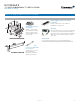
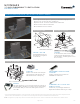
DIMENSIONS
4 1/2”
(114)
16”
(406)
8”
(203)
6 1/2”
(165)
12 1/4”
(311)
17 1/2”
(445)
16”
(406)
14”
(356)
16”
(406)
15”
(380)
3 1/4”
(83)
3 3/4
”
(95)
Measurements
in inches (mm).
Page 5
INSTALL THE
RECIRCULATION BOX
1. Cut opening in cabinet base.
• Size: 14 1/2” (368) x 15” (380)
• Orientation depends upon direction of exhaust.
• Double-check that blower outlet and recirculation box inlet will align.
2. Temporarily place recirculation box into opening in cabinet base.
• Rotate back of box up slightly and insert exhaust end down into opening.
• Mark location of exhaust opening in toe space, rear, or side of cabinet.
3. Remove recirculation box from opening.
4. Cut exhaust opening.
• Size: 3 1/2” (89) x 14 1/4” (362)
• This opening will be covered with decorative grille.
5. Replace recirculation box into opening in cabinet base.
• If necessary, attach a length 3 1/4” (83) x 14” (356) duct extension (not
included) to extend from recirculation box outlet to decorative grille
location.
• Seal the duct connection(s) with aluminum tape to make them secure and
air tight. Do not use duct tape.
• Use 6 - #10 x .625” screws to secure recirculation box to cabinet base.
6. Install blower.
• See blower instructions.
• Use 8” (203) round duct to connect blower exhaust to recirculation box
inlet
• Seal the duct connections with aluminum tape to make them secure and
air tight. Do not use duct tape.
• Drill 1/8” (3) pilot holes through top of recirculation box and attach legs
to recirculation box with 4 - #8 x .375” screws.
7. Install decorative grille.
• Use screws provided.
8.
•
•
•
CUSTOM-MADE
DECORATIVE GRILLE
You can make your own decorative grille. Use the decorative grille in
this kit as a template for the overall size and mounting hole locations.
The grille opening pattern is up to you.
2
min.
FILTER REPLACEMENT
6 months. However, this may vary, depending upon the type and
amount of cooking you do. Call customer service or your local
ALIGN BLOWER
OUTLET WITH
RECIRCULATION
BOX INLET
METAL 8” ROUND DUCT
(per local codes)
EXHAUST THROUGH
CABINET FRONT (TOE KICK)
BLOWER
EXHAUST THROUGH
CABINET SIDE
EXHAUST THROUGH
CABINET BACK
Blower mounted
to downdraft using
mounting legs.
BLOWER
Blower mounted to
framing in remote
location - using
mounting brackets.
MOUNTING
LEGS
Blower outlet and
recirculation box
inlet must align.
(See below.)
OPTIONAL REMOTE BLOWER MOUNT
EXHAUST
THROUGH
CABINET
BACK
EXHAUST
THROUGH
CABINET
SIDE
15"
(380)
14 1/2"
(368)
3 1/2" (89) x 14 1/4" (362)
EXHAUST OPENING
DECORATIVE
GRILLE
15"
(380)
14 1/2"
(368)
3 1/2" (89) x 14 1/4" (362)
EXHAUST OPENING
DECORATIVE
GRILLE
Measurements
in inches (mm).
DIMENSIONS
4 1/2”
(114)
16”
(406)
8”
(203)
6 1/2”
(165)
12 1/4”
(311)
17 1/2”
(445)
16”
(406)
14”
(356)
16”
(406)
15”
(380)
3 1/4”
(83)
3 3/4
”
(95)
Measurements
in inches (mm).
*For front downward ducting applications, electrical panel must be remotely mounted.
Optional 5' extension cable EXTNCE5 accessory is available to connect remotely placed
electrical panel to downdraft. Refer to installation manual.
REQUIRED BLOWER
VTD600P – 600 CFM
600 CFM exible blower
can be installed as an
integrated or inline blower
10
3
/
8
"
(264 mm)
12
3
/
4
"
(324 mm)
12
3
/
4
"
(324 mm)
7
3
/
8
"
(187 mm)
11
5
/
8
"
(295 mm)
5
1
/
4
"
(133 mm)
5
1
/
8
"
(130 mm)
11
5
/
8
"
(295 mm)
5"
(127 mm)
measurements in inches (mm)
10
3
/
8
"
(264 mm)
12
3
/
4
"
(324 mm)
12
3
/
4
"
(324 mm)
7
3
/
8
"
(187 mm)
11
5
/
8
"
(295 mm)
5
1
/
4
"
(133 mm)
5
1
/
8
"
(130 mm)
11
5
/
8
"
(295 mm)
5"
(127 mm)
measurements in inches (mm)
REQUIRED ACCESSORIES
OPTIONAL ACCESSORIES
EXTNCE5
This cable extends 5 ft. to move the electrical panel
out of the way to offer full installation exibility in
any ducting scenario while installing the downdraft.
Ability to connect two cables together to make a
10 ft. cable.
REPLACEMENT CHARCOAL FILTER
UCVFILTER
Includes 1 replacement charcoal lter for
UCVRECIRC recirculation kit
RECIRCULATION KIT
UCVRECIRC
Includes 1 charcoal lter
and 1 metal grill vent plate
(blower sold separately).
Use with induction/electric
cooktops only
DOWNDRAFT GAS COOKTOP SEAL TRIM
KIT UCV36ST
Includes trim, seal, metal grill, and fasteners.
Required for installations with 36" gas cooktops.