
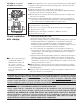
- Form RZ-NA-I-LDAP, P/N 207733 (Rev 2), Page 1 APPLIES TO: Model LDAP Installation/Operation FORM RZ-NA I-LDAP CQS C ONVERGEN T Q UALITY SYSTE M P RODUCT A G ENCY CUSTOMER START-UP WARRA NTY PROCES S Index (by page) Burners , 33 Burner Orifice California Warning Label Clearances Installation Codes Combustion Air Confined Space Destratification Dimensions Electrical Connections Fan , 36 Fan Control (Destratification) , 38 Fan Motor , 36 Gas Piping and Pressures

Form RZ-NA-I-LDAP, P/N 207733 (Rev 2), Page 39
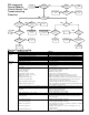
Trial for
Ignition
Call for Heat
Is there a
spark across gap at
ignitor?
Does gas
ignite?
Is there minimum
flame current at the flame
sensor?
Is there
minimum flame current
at the control
module?
Replace control
module.
Check connections to
flame sensor or
moisture in bulkhead
connector.
Is the flame sensor
corroded?
Clean
flame
sensor.
Is the sensor
located in flame
correctly?
Replace flame
sesnsor.
Repositon flame
sensor.
Is gas flowing?
Is the ignitor
position correct in the
gas flow?
Check gas pressure and
supply voltage. If either
are low, correct and
repeat startup.
Reposition spark
ignitor.
Is there
24VAC at the gas
valve?
Is there 24VAC from
gas valve output on control
module to chassis?
Check wiring and
connections to gas
valve.
Replace ignition
control module.
Replace gas valve.
Is there
spark voltage at
control?
Check high
voltage wire
continuity.
Is there
24V P1-2 to power
control?
Replace control
module.
Check wiring and/or
24VAC transformer
output.
YES
NO
YES NO
YES
NO
YES
NO
YES
NO
YES
NO
YES NO
YES
NO
NO
YES
YES
NO
YES
NO
YESNO
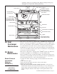
DSI Integrated
Control Module
(Circuit Board) Trial
Troubleshooting
Flowchart
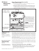
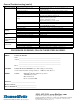
PROBLEM PROBAB LE CAUS E REMEDY
1.
No
p
ower to unit.
1.
Turn on
p
ower; check su
pp
l
y
fuses or main circuit breaker.
2.
No 24 volt
p
ower to inte
g
rated circuit board.
2.
Turn u
p
thermostat; check control transformer out
p
ut.
3.
Inte
g
rated circuit board fuse blown.
3.
Correct cause. Re
p
lace fuse
(
t
yp
e ATC or ATO, 32VDC, 3A
)
.
4.
No
p
ower to venter motor.
4.
Ti
g
hten connections at circuit board and/or motor terminals.
5.
Inte
g
rated circuit board defective.
5.
Re
p
lace inter
g
rated circuit board.
6.
Defective venter motor.
6.
Re
p
lace venter motor. See Para
g
ra
p
h 32.
Burner will 1.
Manual valve not o
p
en.
1.
O
p
en manual valve.
not li
g
ht 2.
Air in the
g
as line.
2.
Bleed
g
as line
(
initial startu
p
onl
y)
.
3.
Gas pressure too high or too low.
3.
Supply pressure should be 5" - 14" w.c. for natural gas or 11" - 14"
w.c. for
p
ro
p
ane
g
as.
4.
No S
p
ark:
4.
a
)
Loose wire connections. a
)
Be certain all wire connections are solid.
b)
Transformer failure.
b)
Be sure 24 volts is available.
c
)
Incorrect s
p
ark
g
a
p
.c
)
Maintain s
p
ark
g
a
p
at 1/8".
d
)
S
p
ark cable shorted to
g
round. d
)
Re
p
lace worn or
g
rounded s
p
ark cable.
e
)
S
p
ark electrode shorted to
g
round. e
)
Re
p
lace if ceramic s
p
ark electrode is cracked or
g
rounded.
f
)
Burner not
g
rounded. f
)
Make certain inte
g
rated circuit board is
g
rounded to i
g
nitor.
g)
Circuit board not
g
rounded.
g)
Make certain inte
g
rated circuit board is
g
rounded to furnace chassis.
h.) Unit not properly grounded. h.) Make certain unit is properly field grounded to earth ground and
p
ro
p
erl
y
p
hased
(
L1 to hot lead L2 to neutral
)
.
i
)
Inte
g
rated circuit board fuse blown. i
)
Correct cause. Re
p
lace fuse
(
t
yp
e ATC or ATO, 32VDC, 3A
)
.
j.) Faulty intergrated circuit board. j) If 24 volt is available to the integrated circuit board and all other causes
have been eliminated, re
p
lace board.
5.
Lockout device interru
p
tin
g
control circuit b
y
above causes.
5.
Reset lockout b
y
interru
p
tin
g
control at the thermostat or main
p
ower.
6.
Combustion air
p
rovin
g
switch
6.
not closin
g
.a
)
Make sure unit is
p
ro
p
erl
y
vented.
b)
Remove obstructions from vent.
c
)
Re
p
lace fault
y
tubin
g
to
p
ressure switch.
7.
Fault
y
combustion air
p
rovin
g
switch.
7.
Re
p
lace combustion air
p
rovin
g
switch.
8.
Main valve not o
p
eratin
g
.
8.
a) Defective valve. a) If 24 volt is measured at the valve connections and valve remains
closed, re
p
lace valve.
b)
Loose wire connections
b)
Check and ti
g
hten all wirin
g
connections.
9.
Integrated circuit board does not power main valve.
9.
a
)
Loose wire connections. a
)
Check and ti
g
hten all wirin
g
connections.
b) Flame sensor grounded.
b
) Be certain flame sensor lead is not grounded or insulation or ceramic is
not cracked. Replace as required.
c) Incorrect gas pressure. c) Supply pressure should be 5" - 14" w.c. for natural gas or 11" - 14"
w.c. for propane gas.
d
)
Cracked ceramic at sensor. d
)
Re
p
lace sensor.
Venter motor will
not start
General Troubleshooting