cable SATELLITE telecom terrestrial THG540 - Voice Over IP Cable Modem User manual Downloaded from www.Manualslib.
Important Information CAUTION CAUTION Disconnect power before To ensure reliable operation and to prevent servicing. overheating, provide adequate ventilation for this modem and keep it away from heat sources. Do not locate near heat registers or other heat-producing equipment. Provide for free air flow around the cable CAUTION This device is intended for modem and its power supply. indoor operation only. Telephone jacks Line 1 and Line 2 must not be connected to outside wiring.
Important Information Operating Information Operating Temperature: 0˚ - 40˚ C (32˚ - 104˚ F) Storage Temperature: -30˚ to 65˚ C If you purchased this product at a retail outlet, please read the following: Product Information Keep your sales receipt to obtain warranty parts and service and for proof of purchase. Attach it here and record the serial and model numbers in case you need them. The numbers are located on the back of the product. Model No.
Table of Contents Chapter 1: Connections and Setup ........................................................................................... 1 Introduction ............................................................................................................................ 1 Voice over IP Cable Modem Features ................................................................................. 1 What’s on the CD-ROM .......................................................................................
Table of Contents Connecting More Than Two Computers to the Cable Modem ........................................... 22 Telephone or Fax Connection .......................................................................................... 23 Activating the Cable Modem .................................................................................................. 24 Chapter 2: Additional Information .........................................................................................
Chapter 1: Connections and Setup Chapter 1: Connections and Setup Introduction Voice over IP Cable Modem Features z Provides two-line telephone service z Capable of receiving data at rates of up to 38 Megabits per second z Able to send and receive data over the cable line z Able to connect multiple computers through Ethernet, USB at the same time (if applicable and your service provider offers multiple computer connections) z Plug-and-play operation for easy setup and installation What’s on the CD
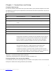
Chapter 1: Connections and Setup Computer Requirements For the best possible performance from your cable modem, your personal computer must meet the following minimum system requirements (note that the minimum requirements may vary by the cable company): IBM PC COMPATIBLE MACINTOSH** CPU Pentium preferred PowerPC or higher System RAM 16MB (32MB preferred) 24MB (32MB preferred) Operating System Windows* NT/2000/Me/XP, Mac OS** 7.6.
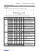
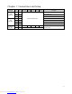
Chapter 1: Connections and Setup Cable Modem Overview Front Panel The following illustration shows the front panel of the EMTA machine: The LEDs on the front panel are described in the table below (from left to right): THG540 Start-up Operation Normal Operation No service Operation 3 Tel 2 Tel 1 Message Cable Activity Cable Link PC Link Internet X X OFF OFF OFF OFF FLASH X X OFF OFF OFF FLASH Ranging - Awaiting Response FLASH (DS carrier acquire, ranging in process but RNG-RSP has
Chapter 1: Connections and Setup THG540 Tel 2 Tel 1 Message Cable Activity Cable Link PC Link OFF FLASH MTA FLASH OFF initialization FLASH FLASH MTA Operation Description MTA DHCP MTA SNMP/TFTP RSIP ON ON ON FLASH Tel1 Off-hook, Tel2 On-hook FLASH ON Tel1 On-hook, Tel2 Off-hook FLASH FLASH SW Download Operation Internet ON FLASH FLASH ON Both Lines On-Hook Both Lines Off-Hook FLASH FLASH FLASH FLASH From Right to Left FLASH A software download and while upda
Chapter 1: Connections and Setup Rear Panel 5 12VDC: 12V Power connector Reboot EMTA: Reboot this device Telephony (LINE1/LINE2): RJ-11 Phone set connector ETHERNET: Ethernet 10/100BaseT RJ-45 connector USB: USB Connector CABLE: F-Connector Illustrations contained in this document are for representation only. Downloaded from www.Manualslib.
Chapter 1: Connections and Setup Wall Mounting The number of the screw: 2 pcs Direction for wall mounting: LED panel upward. Dimension for the screw: TBD There are 4 slots on the underside of the EMTA that can be used for wall mounting. Note: When wall mounting the unit, ensure that it is within reach of the power outlet. You will need 2 suitable screws which screw diameter would be 4.4 mm to wall mount the Cable Modem or the Battery Pack.
Chapter 1: Connections and Setup Relationship among the Devices This illustration shows a cable company that offers Euro-DOCSIS compliant voice/data services. What the Modem Does The voice over IP cable modem is a residential voice-enabled cable modem that provides voice and high-speed data services over cable via your Telephony and Internet Service Providers (TSPs/ ISPs).
Chapter 1: Connections and Setup internet service work for you. Contact Your Local Cable Company You will need to contact your cable company to establish an internet account before you can use your modem.
Chapter 1: Connections and Setup Please verify the following with the cable company The cable service to your home supports Euro-DOCSIS or DOCSIS compliant two-way modem access (note on frequencies for DOCSIS usage). Your internet account has been set up. (The Media Terminal Adapter will provide data service if the cable account is set up but no telephony service is available.) You have a cable outlet near your PC and it is ready for cable modem service.
Chapter 1: Connections and Setup Connecting the Cable Modem to a Single Computer This section of the manual explains how to connect your cable modem to the USB or Ethernet port on your computer and install the necessary software. Please refer to Figure 1 to help you connect your cable modem for the best possible connection. Attaching the Cable TV Wire to the Cable Modem 1. Locate the Cable TV wire. You may find it one of three ways: a. Connected directly to a TV, a Cable TV converter box, or VCR.
Chapter 1: Connections and Setup Important Connection Information The cable modem supports Ethernet and USB connections simultaneously. USB Connection to One Computer Note: Only use the power supply provided with this unit. Using other power supplies may damage the unit. Fig. 2: USB Connection If you received an Installation/Quick Start kit with the purchase of your modem, you should use the software provided in that kit.
Chapter 1: Connections and Setup 1. Before you begin, close all open applications and dialog boxes as they may interfere with your Voice over IP Cable Modem installation. 2. Insert the CD into the CD-ROM drive of your computer. A menu of options appears. 3. Click “Install RCA Cable Modem.” If the options menu does not automatically appear: A. Go to the “Start” menu on the Windows menu bar, then click “Run.” B. Type the letter of your CD-ROM drive followed by :\Thomson.exe. C.
Chapter 1: Connections and Setup 9. Connect one end of the USB cable included with your Voice over IP Cable Modem to the USB port on your computer. Connect the other end of the USB cable to the USB port on the Voice over IP Cable Modem. 10. If the modem is detected, the “Windows Found New Hardware” window appears and the “Installation Complete” screen appears.
Chapter 1: Connections and Setup Note: If Windows 2000 does not recognize the Voice over IP Cable Modem’s presence, your BIOS settings may not permit USB and/or Plug-and-Play devices. Please contact your computer’s customer service department. 7. Choose the “Search for a suitable driver for my device (recommended)” option, and click “Next”. 8. Choose ONLY the “CD-ROM” option and click “Next”. 14 Downloaded from www.Manualslib.
Chapter 1: Connections and Setup 9. The search should find the driver for the “Thomson USB CDC Devices”. To confirm that this is the case, click “Next” to continue and proceed to step 11. Otherwise, see step 10. Important: Do NOT continue if the search finds “USB Composite Device” driver. Proceed to step 10. 10. Follow these instructions ONLY if the driver found was NOT the “Thomson USB CDC Devices.” A. Click “Back” to return to the previous window. B. Ensure that you have selected the “CD-ROM” option. C.
Chapter 1: Connections and Setup install the driver. At this point your PC needs to copy Windows 2000 specific files. If these files are not located on your hard drive, you may need to insert your Windows 2000 installation media (i.e., Windows 2000 CD-ROM), but first remove the Voice over IP Cable Modem CD-ROM. 12. After the Windows specific files are copied, you may be asked for another USB driver file named “NETRCACM.SYS,” located on the Voice Over IP Cable Modem CD-ROM.
Chapter 1: Connections and Setup Choose the “Automatic search for a better driver (Recommended)” option, and click “Next.” Note: If Windows Me does not recognize the Voice over IP Cable Modem’s presence, i.e., the “Add New Hardware Wizard” did not automatically appear, your BIOS settings may not permit USB and/or Plug-and-Play devices. Please contact your computer’s customer service department. 7. The automatic search should find and install the driver for the “RCA or Thomson USB Cable Modem”.
Chapter 1: Connections and Setup software automatically (Recommended)” option, and click “Next.” Note: If Windows XP does not recognize the Voice over IP Cable Modem’s presence, i.e., the “Welcome to the New Hardware Wizard” did not automatically appear, your BIOS settings may not permit USB and/or Plug-and-Play devices. Please contact your computer’s customer service department. 7. Your computer will install the drivers for the “RCA or Thomson USB Cable Modem”. Click on “Next” to complete the process.
Chapter 1: Connections and Setup 9. The Voice over IP Cable Modem installation is now complete. To validate a proper installation, perform the following instructions: A. Click on the “Start” icon in the lower left-hand corner of your screen. B. Select “Settings,” followed by “Control Panel.” The “Control Panel” window will appear. C. Double-click on the “System” icon, and select the “Device Manager.” D. Scroll down the list until you come to “Network Adapters.” Double-click on “Network Adapters.” E.
Chapter 1: Connections and Setup Below are important points to remember before you connect the Voice over IP Cable Modem: For Ethernet connections, go to page 21. For telephone and fax connections, go to page 23. 20 Downloaded from www.Manualslib.
Chapter 1: Connections and Setup Ethernet Connection to One Computer Make the connections to the modem in the following sequence: 1. Connect one end of the coaxial cable to the cable connection in the wall, and the other end to the CABLE jack on the cable modem. 2. Connect the plug from the AC power supply into the POWER AC ADAPTER jack on the cable modem, and plug the power supply into an AC outlet. Note: Use only the power supply that accompanied this unit. Using other adapters may damage the unit. 3.
Chapter 1: Connections and Setup Connecting More Than Two Computers to the Cable Modem If you need to connect more than two computers or if you need to connect two computers, but USB is not available, you’ll need the following additional equipment: Crossover-wired, or “null,” category 5 Ethernet cable for the cable modem to be connected to the hub 10BaseT or 100BaseT Hub or Switch Straight through, or standard, category 5 Ethernet cable (one for each computer to be connected) If you have a hub w
Chapter 1: Connections and Setup Telephone or Fax Connection When properly connected, most telephony devices can be used with the cable modem just as with conventional telephone service. To make a normal telephone call, pick up the handset, wait for a dial tone, and then dial the desired number. For services such as call waiting, use the hook switch (or FLASH button) to change calls. The following procedures describe some of the possible connection schemes for using telephony devices with the cable modem.
Chapter 1: Connections and Setup Activating the Cable Modem After you install the cable modem and turn it on for the first time (and each time the modem is reconnected to the power), it goes through several steps before it can be used. Each of these steps is represented by a different pattern of flashing lights on the front of the modem. Note: All indicators flash once prior to the initialization sequence.
Chapter 2: Additional Information Chapter 2: Additional Information Frequently Asked Questions Q. What if I don’t subscribe to cable TV? A. If cable TV is available in your area, data and voice service may be made available with or without cable TV service. Contact your local cable company for complete information on cable services, including high-speed internet access. Q. How do I get the system installed? A. Professional installation from your cable provider is strongly recommended.
Chapter 2: Additional Information General Troubleshooting You can correct most problems you have with your product by consulting the troubleshooting list that follows. I can’t access the internet. z Check all of the connections to your cable modem. z Your Ethernet card or USB port may not be working. Check each product’s documentation for more information. z The Network Properties of your operating system may not be installed correctly or the settings may be incorrect.
Chapter 2: Additional Information z Verify that the cable modem service is Euro-DOCSIS or DOCSIS compliant by calling your cable provider (DOCSIS will only work if the used frequencies are between 93-861MHz). I don’t hear a dial tone when I use a telephone. z Telephone service is not activated. If the rightmost light on the cable modem stays on while others flash, check with your TSP or cable company.
Chapter 2: Additional Information Service Information If you purchased or leased your cable modem directly from your cable company, then warranty service for the cable modem may be provided through your cable provider or its authorized representative. For information on 1) Ordering Service, 2) Obtaining Customer Support, or 3) Additional Service Information, please contact your cable company. If you purchased your cable modem from a retailer, see the enclosed warranty card. 28 Downloaded from www.
Chapter 2: Additional Information Glossary 10BaseT – Unshielded, twisted pair cable with an RJ-45 connector, used with Ethernet LAN (Local Area Network). “10” indicates speed (10 Mbps), “Base” refers to baseband technology, and “T” means twisted pair cable. Authentication - The process of verifying the identity of an entity on a network. DHCP (Dynamic Host Control Protocol) – A protocol which allows a server to dynamically assign IP addresses to IP device on the fly.
Chapter 2: Additional Information NID - Network Interface Device, the interconnection between the internal house telephone wiring and a conventional telephone service provider’s equipment. These wiring connections are normally housed in a small plastic box located on an outer wall of the house. It is the legal demarcation between the subscriber’s property and the service provider’s property.
Fore more information Thomson | 46, quai Alphonse Le Gallo | 92100 Boulogne-Billancourt | France Tel. : 33 (0) 1 41 86 50 00 | Fax : 33 (0) 1 41 86 56 59 | www.thomson-broadband.com © 2007 Thomson Inc.- Trademark(s) ® Registered\ -Marca(s) Registada(s)\ Photos and features subject to change without notice. Illustration of product finish may vary from actual color. Downloaded from www.Manualslib.