Owner’s Manual For professional use only Do not use this equipment before reading this manual! 840 ix Airless Sprayer Model Number: High Rider Bare High Rider Complete Low Rider Bare Low Rider Complete Printed in the U. S. A. 800-2000 800-2005 800-2010 800-2015 NOTE: This manual contains important warnings and instructions. Please read and retain for reference. 0104 © 2004 Titan Tool Inc. All rights reserved. Form No.
Table of Contents • NEVER allow any part of the body to touch the fluid stream. DO NOT allow body to touch a leak in the fluid hose. • NEVER put hand in front of the gun. Gloves will not provide protection against an injection injury. • ALWAYS lock gun trigger, shut pump off, and release all pressure before servicing, cleaning tip or guard, changing tip, or leaving unattended. Pressure will not be released by turning off the motor.
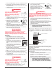
Grounding Instructions GAS ENGINE (WHERE APPLICABLE) Always place sprayer outside of structure in fresh air. Keep all solvents away from engine exhaust. Never fill fuel tank with a running or hot engine. Hot surface can ignite spilled fuel. Always attach ground wire from pump to a grounded object. Refer to engine owner’s manual for complete safety information. HAZARD: EXPLOSION HAZARD DUE TO INCOMPATIBLE MATERIALS - will cause severe injury or property damage.
General Description CAUTION This airless sprayer is a precision power tool used for spraying many types of materials. Read and follow this instruction manual carefully for proper operating instructions, maintenance, and safety information. Always use a minimum 12 gauge, three-wire extension cord with a grounded plug. Never remove the third prong or use an adapter.
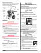
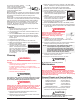
7. Move the PRIME/SPRAY valve up to the SPRAY position. 8. Turn the unit on and set the pressure to minimum by turning the pressure control knob to the “Min PSI” setting in the yellow zone. 9. Unlock the gun by turning the gun trigger lock to the unlocked position. 12. Lock the gun by turning the gun trigger lock to the locked position. 13. Turn the unit off by moving the pressure control knob to the OFF position in the black zone. Trigger lock 14. Attach tip guard and tip to the gun as in locked position.
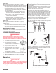
Spraying Technique Solid Yellow When the pressure indicator is solid yellow, the sprayer is operating between 200 and 1800 PSI. A solid yellow pressure indicator means: • The sprayer is at the proper pressure setting for spraying stain, lacquer, varnish, and multi-colors. • If the pressure indicator goes to solid yellow when the pressure is set so that it starts at solid green, it indicates one of the following: a. Tip Wear Indicator — when spraying with latex or at high pressure the solid yellow appears.
3. Place the siphon tube into a container of the appropriate solvent. Examples of the appropriate solvent are water for latex paint or mineral spirits for oil-based paints. 4. Place the return hose into a metal waste container. 5. Move the PRIME/SPRAY valve down to its PRIME position. 6. Turn the unit on and set the pressure to Turbo PulseClean by turning the pressure control knob to its CLEAN position in the red zone. 7.
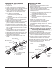
Replacing the Filters 2. Test your repair before regular operation of the sprayer to be sure that the problem is corrected. If the sprayer does not operate properly, review the repair procedure to determine if everything was done correctly. Refer to the Troubleshooting Charts to help identify other possible problems. 3. Make certain that the service area is well ventilated in case solvents are used during cleaning. Always wear protective eyewear while servicing.
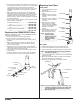
Replacing the Motor Assembly (with Electronic Control) Replacing the Gears 1. Unplug the unit. 2. Loosen and remove the four motor shroud screws. Remove the motor shroud. 3. Release the tie wrap on the top of the baffle assembly and slip the baffle assembly down off of the motor. 4. Loosen and remove the three electronic cover screws. Lift the electronic cover off of the electronic control assembly on the motor. 5. At the electronic control assembly: a.
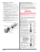
Replacing the Transducer Servicing the Fluid Section 1. Unplug the unit. 2. Loosen and remove the four motor shroud screws. Remove the motor shroud. 3. At the electronic control assembly, disconnect the black wire coming from the transducer. 4. Pull the grommet out of the mounting plate and slide it up the shaft of the transducer until it is clear of the mounting plate. 5. Using a wrench, loosen and remove the transducer from the filter housing.
NOTE: During reassembly, make sure the Viton o-rings and the Teflon back-up rings between the upper housing and lower housing as well as between the lower housing and the foot valve housing are lubricated with grease and in position. 16. Pre-form the lower packing using Install lower packing with the lower packing sizing tool the side that has the o-ring (included in the repacking kit). closest to the face of the packing facing up. 17.
Troubleshooting Airless Sprayer Problem Cause Electric motor won't run 1. 2. 3. 4. 5. Sprayer won’t prime 1. Air in line Solution Unit unplugged or circuit fuse blown Pressure setting too low Electric motor burned out Switch defective Circuit breaker on sprayer tripped 1. 2. 3. 4. 5. Check Increase Replace Replace Reset the breaker 2. Insufficient pressure 1. Check siphon tube o-ring and/or let paint circulate in prime position 2. Increase pressure Insufficient material flow 1. 2. 3. 4.
Troubleshooting Spray Patterns Problem Cause Solution Tails 1. 2. 3. 4. 5. Inadequate fluid delivery Fluid not atomizing Insufficient velocity Material too cohesive Tip worn past sprayer capacity Heavy centered pattern 1. Worn tip 2. Tip may be chipped 1. Replace 2. Replace Distorted pattern 1. Plugged, worn or chipped tip 1. Clean or replace Pattern expanding and contracting (Surge) 1. Leak in suction tube 2. Not enough hose 1. Tighten 2.
Consignes de sécurité AVERTISSEMENT AUX MÉDECINS : Une perforation sous-cutanée constitue un traumatisme. Il est important de traiter la blessure de façon chirurgicale aussitôt que possible. NE RETARDEZ PAS ce traitement pour des recherches de toxicité. La toxicité n'est un risque que dans les cas où certains produits de revêtement pénètrent dans le flux sanguin. Il peut être nécessaire de faire appel à des soins de chirurgie plastique ou de reconstruction de la main.
Instructions de mise à la terre MOTEUR À ESSENCE (DANS LES CAS OÙ CELA S’APPLIQUE) Toujours placer la pompe à l’extérieur de la structure à l’air frais. Garder tous les solvants loin de l’échappement du moteur. Ne jamais remplir le réservoir à carburant lorsque le moteur est en marche ou lorsqu’il est chaud ; les surfaces chaudes risquent d’enflammer le carburant déversé accidentellement.
Precauciones de seguridad NOTA PARA EL MÉDICO: La inyección dentro de la piel es una lesión traumática. Es importante que la lesión se trate quirúrgicamente tan pronto como sea posible . NO retrase el tratamiento por investigar la toxicidad. La toxicidad es motivo de preocupación con algunos revestimientos que se inyectan directamente en la corriente sanguínea. Es recomendable consultar a un cirujano plástico o reconstructor de manos.
Instrucciones para conectar a tierra PELIGRO: PELIGRO DE EXPLOSIÓN DEBIDO A MATERIALES INCOMPATIBLES - Podría causar lesiones severas o daños en la propiedad. PARA PREVENIR: • No utilice materiales que contengan blanqueador o cloro. • No use solventes con hidrocarburos halogenados, tales como productos para eliminar el moho, cloruro de metileno y 1,1,1 - tricloroetano. Estos no son compatibles con el aluminio.
Parts List Main Assembly 1 2 3 15 4 16 17 5 18 6 19 7 8 9 10 11 12 13 20 21 14 Item 1 2 3 4 5 6 7 8 9 10 11 Part # 800-600 800-036 ---------761-178 800-324 763-551 858-625 800-328 800-300 451-241 730-334 Description Quantity Cart assembly.............................................1 Grommet.....................................................2 Drive assembly ...........................................1 Screw..........................................................4 Pail hook ................
Drive Assembly 1 2 3 4 34 5 6 35 7 36 8 37 38 9 19 20 21 22 23 10 11 12 24 25 26 27 28 13 14 39 40 29 30 31 32 33 15 16 17 18 Item 1 2 3 4 5 6 7 8 9 10 11 12 13 14 15 16 17 18 19 20 21 Part # 800-078 800-205 800-264 800-256 800-525 800-541 800-261 800-262 800-259 800-510 800-253 700-283 800-265 800-284 800-382 800-753 800-202 800-276 704-229 765-327 800-075 Description Quantity Electronic cover ..........................................1 Screw................................................
Fluid Section Assembly (P/N 800-300) Install upper packing with raised lip facing down. 1 2 3 Raised Lip 4 Closer Top 5 6 Install lower packing with the side that has the o-ring closest to the top of the packing facing up. 7 8 9 10 22 11 12 13 14 15 16 17 NOTE: When repacking the fluid section, make sure the raised lip on the bottom of the lower packing is fully outside the packing around the piston rod after insertion of the piston rod. 18 19 20 7 8 21 20 © Titan Tool Inc.
Item 1 2 3 4 5 6 7 8 9 10 11 12 13 Part # 800-325 800-327 800-248 800-351 800-250 800-354 800-332 800-333 800-352 800-246 800-348 800-244 800-247 Description Quantity Upper seal retainer .....................................1 Spacer ........................................................1 Upper packing assembly ............................1 Upper housing ............................................1 Lower packing assembly ............................1 Wear ring ...........................................
Siphon Set (low rider) Item 1 2 3 4 5 6 7 1 Description Quantity Return hose ................................................1 Siphon hose................................................1 Swivel .........................................................1 Inlet screen .................................................1 Clamp .........................................................1 Siphon hose adapter ..................................1 Tie wrap (not shown) ..................................
PRIME/SPRAY Valve Assembly (P/N 800-915) Accessories Airless Tip Selection Tips are selected by the orifice size and fan width. The proper selection is determined by the fan width required for a specific job and by the orifice size that will supply the desired amount of fluid and accomplish proper atomization. For light viscosity fluids, smaller orifice tips generally are desired. For heavier viscosity materials, larger orifice tips are preferred. Please refer to the chart below.
Warranty Titan Tool, Inc., (“Titan”) warrants that at the time of delivery to the original purchaser for use (“End User”), the equipment covered by this warranty is free from defects in material and workmanship.