
Paint Sprayer User Manual
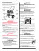
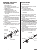

Replacing the Transducer
1. Unplug the unit.
2. Loosen and remove the four motor shroud screws.
Remove the motor shroud.
3. At the electronic control assembly, disconnect the black
wire coming from the transducer.
4. Pull the grommet out of the mounting plate and slide it up
the shaft of the transducer until it is clear of the mounting
plate.
5. Using a wrench, loosen and remove the transducer from
the filter housing. Carefully thread the transducer wire out
through the mounting plate.
6. Slide the grommet off of the old transducer and onto the
new transducer.
7. Thread the new transducer wire through the mounting
plate and up to the electronic control assembly.
8. Thread the new transducer into the filter housing and
tighten securely with a wrench.
9. Push the grommet into the mounting plate.
10. Connect the transducer wire to the electronic control
assembly (refer to the electrical schematic in the Parts List
section of this manual).
11. Slide the motor shroud over the motor. Make sure the
shroud gasket is positioned properly.
12. Secure the motor shroud with the four motor shroud
screws.
Motor Shroud
Transducer
Grommet
Motor Shroud Screws
Electronic Control
Assembly
Mounting Plate
To Filter
NOTE: Make sure the o-ring on the transducer is in
place before threading the transducer into the
filter housing.
10 ©Titan Tool Inc. All rights reserved.
Servicing the Fluid Section
Use the following procedures to service the valves and repack
the fluid section. Perform the following steps before
performing any maintenance on the fluid section.
1. Loosen and remove the four front cover screws. Remove
the front cover.
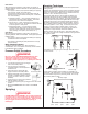
2. Position the crankshaft/slider assembly at the bottom,
dead-center of its stroke so that the connecting pin and
retaining ring are visible below the slider assembly. This
is done by turning the sprayer on and off in short bursts
until the connecting pin is visible below the slider housing.
3. Turn off and unplug the unit.
Before proceeding, follow the Pressure Relief Procedure
outlined previously in this manual. Additionally, follow all
other warnings to reduce the risk of an injection injury,
injury from moving parts or electric shock. Always unplug
the sprayer before servicing!
4. Remove the return hose from the clamp on the siphon
tube.
5. Unscrew the siphon tube/siphon set from the foot valve.
6. Loosen and remove the high-pressure hose from the
nipple on the back of the upper housing of the fluid
section.
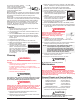
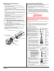
Servicing the Valves
The design of the fluid section
allows access to the foot valve and
seat as well as the outlet valve and
seat without completely
disassembling the fluid section. It
is possible that the valves may not
seat properly because of debris
stuck in the foot valve seat or outlet
valve seat. Use the following
instructions to clean the valves and
reverse or replace the seats.
1. Loosen and remove the foot
valve housing from the lower
housing.
2. Clean out any debris in the foot
valve housing and examine the
housing and the foot valve
seat. If the seat is damaged,
reverse or replace the seat.
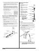
3. Using two wrenches, hold the
upper housing at the wrench
flats with one wrench and loosen the lower housing with
the other. Remove the lower housing.
4. Using a 3/4” wrench, loosen and
remove the outlet valve retainer
from the piston rod.
5. Clean out any debris and
examine the retainer and outlet
valve seat. If the seat is
damaged, reverse or replace the
seat.
6. Remove, clean, and inspect the
outlet valve cage and outlet
valve ball. Replace if they are
worn or damaged.
7. Reassemble the valves by reversing the steps above.
NOTE: Always service the
outlet valve with the
piston rod attached to
the pump. This will
prevent the piston rod
from rotating during
disassembly of the
outlet valve.
Outlet Valve
Retainer
Nylon
Washer
Outlet Valve
Seat
Outlet Valve
Ball
Outlet Valve
Cage
Outlet Valve
Seal
Piston Rod
Upper
Housing
Lower
Housing
Foot Valve
Housing
Viton
O-Ring
O-ring
Teflon
Back-Up
Ring
Foot Valve
Seat
Foot Valve
Ball
Foot Valve
Cage
Lower
Housing
Upper
Housing
WARNING