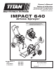
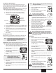
Owner’s Manual Notice d’utilisation Manual del Propietario Do not use this equipment before reading this manual! IMPACT 640 Airless Sprayer NOTE: This manual contains important warnings and instructions. Please read and retain for reference. Model Number: Skid: High Rider: Low Rider: Anti-Theft Digital Lockout Security Code 805-002 805-004 805-005 _ _ _ _ Serial # _ _ _ _ _ _ _ _ _ _ 1010 • © T tan Too Inc. A R ghts Reserved. Form No.
Important Safety Information · Read all safety information before operating the equipment. Save these instructions. This symbol indicates a hazardous situation, which, if not not avoided could result in death or serious injury. HAZARD: HAZARDOUS VAPORS Paints, solvents, insecticides, and other materials can be harmful if inhaled or come in contact with the body. Vapors can cause severe nausea, fainting, or poisoning.
Important Safety Information · Read all safety information before operating the equipment. Save these instructions. Grounding Instructions HAZARD: EXPLOSION HAZARD DUE TO INCOMPATIBLE MATERIALS Will cause property damage or severe injury. PREVENTION: • Do not use materials containing bleach or chlorine. • Do not use halogenated hydrocarbon solvents such as bleach, mildewcide, methylene chloride and 1,1,1 trichloroethane. They are not compatible with aluminum.
Operation Table of Contents Safety Information..................................................................... 2 Specifications............................................................................ 3 General Description.................................................................. 4 Operation.................................................................................... 4 Setup.................................................................................... 4 Preparing to Paint......
Preparing a New Sprayer NOTE: Make sure that the spray gun does not have a tip or tip guard installed. If this sprayer is new, it is shipped with test fluid in the fluid section to prevent corrosion during shipment and storage. This fluid must be thoroughly cleaned out of the system with mineral spirits before you begin spraying. 8. Move the PRIME/SPRAY valve up to the SPRAY position. 9. Turn on the sprayer. 10. Unlock the gun by turning the gun trigger lock to the unlocked position.
12. Trigger the gun into the metal waste container until all air and solvent is flushed from the spray hose and paint is flowing freely from the gun. 13. Lock the gun by turning the gun trigger lock to the locked position. Turn off the sprayer. Attach tip guard and tip to the gun as instructed by the tip guard or tip manuals. 14. 15. • If the pressure indicator goes to solid yellow when the pressure is set so that it starts at solid green, it indicates one of the following: a.
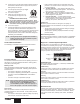
Main Screen Security Code Screen SECURITY CODE The Security Code screen allows the MENU-1 CHANGE-2 user to set a four digit security code to prevent unauthorized use of the sprayer. If a security code has been set, the control system display will ask for the code at startup. If the correct code is entered, the display will show the Main Screen and the sprayer will operate. If the wrong code is entered, the display will continue to ask for the correct code and the sprayer will be disabled.
Avoid arcing or holding the gun at an angle. This will result in an uneven finish. Pressure Relief Procedure Be sure to follow the pressure relief procedure when shutting the unit down for any purpose, including servicing or adjusting any part of the spray system, changing or cleaning spray tips, or preparing for cleanup. 1. 2. 3. 4. 5. 6. 7. 8. Offspray Lock the gun by turning the gun trigger lock to the locked position. Turn off the sprayer by moving the ON/ OFF switch to the OFF position.
11. Turn on the sprayer. Practice 1. 2. 3. 4. 5. 6. 7. 8. Be sure that the paint hose is free of kinks and clear of objects with sharp cutting edges. Set the pressure to minimum by turning the pressure control knob to the “MIN” setting. Move the PRIME/SPRAY valve up to its SPRAY position. Turn the pressure control knob clockwise to its highest setting. The paint hose should stiffen as paint begins to flow through it. Unlock the gun trigger lock. Trigger the spray gun to bleed air out of the hose.
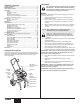
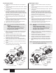
Replacing the Motor 1. 2. 3. 4. 5. 6. 7. 8. Replacing the Gears Perform the Pressure Relief Procedure and unplug the sprayer. Loosen and remove the two motor cover screws. Remove the motor cover. Loosen and remove the three belly pan screws. Remove the belly pan. On the back of the motor, disconnect the wire coming from the potentiometer and the wire coming from the transducer.
Replacing the Transducer 1. 2. 3. Replacing the prime/spray Valve Loosen and remove the four front cover screws. Remove the front cover. Stop the sprayer at the bottom of its stroke so that the piston is in its lowest position. Perform the Pressure Relief Procedure and unplug the sprayer. Perform the following procedure using PRIME/SPRAY valve replacement kit P/N 700-258. 1. Push the groove pin out of the valve handle. 2. Remove the valve handle and the cam base. 3.
7. Servicing the Fluid Section Use the following procedures to service the valves and repack the fluid section. Perform the following steps before performing any maintenance on the fluid section. 1. Loosen and remove the four front cover screws. Remove the front cover. 2. Stop the sprayer at the bottom of its stroke so that the piston is in its lowest position. 3. Perform the Pressure Relief Procedure and unplug the sprayer.
Gun Filter 1. Move the gun trigger lock to the unlocked position. 2. Loosen and remove the handle from the gun body. 3. Turning clockwise, unscrew the filter from the gun body. NOTE: Coat the piston guide tool and the piston rod with grease before inserting them into the pump block. 13. 14. 15. 16. 17. 18. 19. 20. 21. Using a wrench, tighten the retainer nut securely. Slide the top of the piston rod into the T-slot on the slider assembly.
Troubleshooting Problem A. The un t w not run. Cause 1. 2. 3. 1. 2. 3. P ug the un t n. Reset the breaker. Turn the pressure contro knob c ockw se to supp y power to the un t and ncrease the pressure sett ng. 4. 5. 6. Inspect or take to a T tan author zed serv ce center. A ow motor to coo . Rep ace the ON/OFF sw tch. In et va ve s stuck. The PRIME/SPRAY va ve s n the SPRAY pos t on. A r eak n the s phon tube/suct on set. 1. 2. 4. 5. The pump fi ter and/or n et screen s c ogged.
Digi-Trac™ Control System Error Messages The following error message screens appear whenever the DigiTrac™ Control System detects a problem with the sprayer. Once a problem occurs and the error message appears, the sprayer will shut down. Before proceeding, follow the Pressure Relief Procedure outlined previously in this manual. Additionally, follow all other warnings to reduce the risk of an injection injury, injury from moving parts or electric shock.
Parts List • Liste de pièces • Lista de piezas Main Assembly • Vue d’ensemble • Ensamblaje principal 1 11 12 14 13 15 2 16 17 3 18 4 5 19 20 6 21 7 8 22 9 10 24 29 25 23 26 27 28 30 31 cart model Modèle de chariot Modelo de carro 32 33 34 35 36 37 38 44 © Titan Tool Inc. All rights reserved.
Item Article Articulo Part No. Nº de piéce Pieza No.
Skid Assembly • Ensemble de support • Ensamblaje de la soporte Suction Set Assembly (skid and low rider models) Ensemble d’aspiration (support et basse chariot) Ensamblaje del juego de succión (base y bajo carro) 1 1 4 2 5 6 7 8 4 9 3 2 5 10 6 3 7 Suction Set Assembly • Ensemble d’aspiration • Ensamblaje del juego de succión Item Article Articulo Part No. Nº de piéce Pieza No.
Drive Assembly • Boîte d’engrenages • Ensamblaje de la caja de engranajes 3 1 4 5 6 7 8 2 9 10 NOTE: All electrical work should be performed by an authorized service center. NOTA : Tous les travaux d’électricité doivent être effectués par le personnel d’un centre de service autorisé. NOTA: Todo trabajo eléctrico debe realizarlo un centro de servicio autorizado. 11 12 13 Item Article Articulo Part No. Nº de piéce Pieza No.
Fluid Section Assembly • Section de liquides • Sección de líquido (P/N 805-207A: Skid model/Low boy • Support/Bas chariot• Soporte/Bajo carro) (P/N 805-233A: High-rider model • Modèle de chariot • Modelo de carro) 1 Install upper packing with raised lip and O ring facing down. La partie surélevée et le joint torique du tampon supérieur doivent être vers le bas. O-Ring 2 Raised Lip Instale la empaquetadura superior con el reborde levantado y la junta tórica apuntando hacia abajo.
Item Article Articulo Part No. Nº de piéce Pieza No.
Low rider Assembly • Bas chariot • Ensamblaje del bajo carro (P/N 0558392) 1 2 3 9 4 5 10 6 7 8 11 12 14 Item Article Articulo Part No. Nº de piéce Pieza No.
High Rider Assembly • Chariot • Carro (P/N 805-282A) 1 2 8 3 9 4 10 5 6 7 Item Article Articulo Part No. Nº de piéce Pieza No.
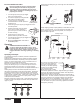
Electrical Schematic • Schéma de raccordement électrique • Esquema eléctrico (P/N 805 363A) Power Cord (skid) Cordon d'alimentation (support) Cable de alimentación (soporte) (P/N 805 404A) Power Cord (cart and lowboy cart) Cordon d'alimentation (chariot et basse chariot) Cable de alimentación (carro y bajo carro) Fuse block Bloc de fusible Bloque de fusible (P/N 0522210) (P/N 9850936) Switch Interrupteur Interruptor (P/N 0522023) Capacitor Capaciteur Capacidor (P/N 800 929) Fuse Fusible Fusible P/N 765-07
English Français Accessories Accessoires Airless Tip Selection Gamme d’embouts à dépression Tips are selected by the orifice size and fan width. The proper selection is determined by the fan width required for a specific job and by the orifice size that will supply the desired amount of fluid and accomplish proper atomization. For light viscosity fluids, smaller orifice tips generally are desired. For heavier viscosity materials, larger orifice tips are preferred. Please refer to the chart below.
Warranty Titan Tool, Inc., (“Titan”) warrants that at the time of delivery to the original purchaser for use (“End User”), the equipment covered by this warranty is free from defects in material and workmanship.