
Product Manual

English
4 © Titan Tool Inc. All rights reserved.
Table of Contents
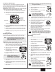
Safety Information .................................................................... 2
Specications ........................................................................... 3
General Description ................................................................. 4
Operation ................................................................................... 4
Setup ................................................................................... 4
Preparing to Paint................................................................ 5
Painting ............................................................................... 5
Control Panel Indicators ...................................................... 6
Digi-Trac™ Control System Operation ............................. 6-7
Pressure Relief Procedure .................................................. 8
Spraying .................................................................................... 8
Spraying Technique ............................................................ 8
Practice ............................................................................... 9
Cleanup ..................................................................................... 9
Maintenance .............................................................................. 9
General Repair and Service Notes...................................... 9
Replacing the Motor .......................................................... 10
Replacing the Gears.......................................................... 10
Replacing the Transducer ................................................. 11
Replacing the PRIME/SPRAY Valve ................................. 11
Servicing the Fluid Section ........................................... 12-13
Replacing the Filters.......................................................... 13
Troubleshooting ..................................................................... 14
Digi-Trac™ Control System Error Messages .................... 15
Parts Listings .......................................................................... 44
Main Assembly .................................................................. 44
Siphon Assembly (skid and low rider assembly) ............... 46
Skid Assembly ................................................................... 46
Drive Assembly ................................................................. 47
Fluid Section Assembly ..................................................... 48
Low Rider Assembly.......................................................... 50
High Rider Assembly ......................................................... 51
Electrical Schematic .......................................................... 52
Labels ................................................................................ 52
Accessories ....................................................................... 53
Warranty .................................................................................. 56
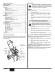
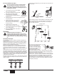
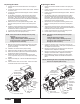
General Description
This airless sprayer is a precision power tool used for spraying
many types of materials. Read and follow this instruction manual
carefully for proper operating instructions, maintenance, and
safety information.
Outlet Fitting
Siphon Tube
Return Tube
ON/OFF
switch
Pressure
Control
Knob
Pusher
Stem
Motor
Oiler Cap
Fluid Section
PRIME /
SPRAY Valve
Oiler
button
Digi-Trac™
Control System
Screen
Operation
This equipment produces a fluid stream at extremely
high pressure. Read and understand the warnings
in the Safety Precautions section at the front of this
manual before operating this equipment.
Setup
Perform the following procedure before plugging in the power
cord of an electric unit.
1. Ensure that the siphon tube and the return hose are
attached and secure.
2. Using a wrench, attach a minimum of 50’ of 1/4” airless
spray hose to the outlet tting on the sprayer. Tighten
securely.
3. Attach an airless spray gun to the spray hose. Using two
wrenches (one on the gun and one on the hose), tighten
securely.
NOTE: Do not attach the tip to the spray gun yet.
Remove the tip if it is already attached.
Make sure all airless hoses and spray guns are
electrically grounded and rated at or above the
maximum operating pressure range of the airless
sprayer.
4. Make sure the pressure control knob is in its OFF position
in the black zone.
5. Make sure the ON/OFF switch is in its OFF position.
6. Remove the ll cap with a straight-slot screwdriver, or a
coin. Fill the oil reservoir with one ounce of piston seal
lubricant (Piston Lube). Replace oiler cap.
7. Press oiler button 2-5 times to prime the oiler. Press once
for every eight hours of usage to lubricate the uid section.
IMPORTANT: Never operate unit for more than ten seconds
without fluid. Operating this unit without fluid will cause
unnecessary wear to the packings.
8. Fully depress the pusher stem to make sure the inlet ball
is free.
9. Make sure the electrical service is 120V, 15 amp
minimum.
10. Plug the power cord into a properly grounded outlet at
least 25’ from the spray area.
IMPORTANT: Always use a minimum 12 gauge, three-wire
extension cord with a grounded plug. Never remove the
third prong or use an adapter.
IMPORTANT: After turning pump off, allow 30 seconds for
the power to completely drain from capacitors.