INSTALLATION INSTRUCTIONS CUSTOM SERIES 36" Wood Burning Fireplaces P/N 700,009M REV. D 11/2003 MODELS RD-36 RD-36-H RDI-36 RDI-36-H HC-36 HC-36-H HCI-36 HCI-36-H This installation manual will enable you to obtain a safe, efficient and dependable installation of your fireplace system. Please read and understand these instructions before beginning your installation. Do not alter or modify the fireplace or its components under any circumstances.
TABLE OF CONTENTS Safety Rules .................................... page 2 Tools and Building Supplies ............ page 2 Precautions ..................................... page 3 Introduction ..................................... page 3 Clearances/Height Requirements ..... page 3 Chimney System ............................. page 3 Assembly Outline ............................. page 4 Location of Fireplace ....................... page 4 Assembly Steps ...............................
Note: Illustrations shown reflect “typical” installations with nominal dimensions and are for design and framing reference only. Actual installations may vary due to individual design preferences. However, always maintain minimum clearances to combustible materials and do not violate any specific installation requirements.
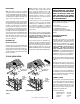
Insulate Joists Same As Ceiling Draft Stops Chimney Height LOCATION OF FIREPLACE The total height of your completed fireplace system from the surface the fireplace rests on to the chimney top must not exceed 60' and must also meet minimum height requirements. Refer to the minimum system height chart. Carefully select the proper location for heat circulation, aesthetics, chimney obstructions and clearance to side wall(s).
ASSEMBLY STEPS Note: The following steps represent the normal sequence of installation. Each installation is unique, however, and might require a different sequence. 1. Position firebox prior to framing or into prepared framing. 2. Install the chimney system. 3. Connect house wiring to the fireplace for later attachment of optional blower. 4. Install optional outside combustion air kit. 5. Plumb gas line if a decorative gas appliance will be used.
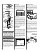
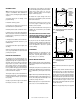
FIREPLACE SPECIFICATIONS 12 ¹⁄₂" (318 mm) 9" (229 mm) 16 ¹⁵⁄₁₆" (428 mm) 1 ¹⁄₂" Metal Safety Strips 36" (914 mm) 20 ³⁄₁₆" (513 mm) Figure 8 44 ¹⁄₄" (1124 mm) 2 ⁷⁄₈" (73 mm) 7 ¹⁄₈" (181 mm) Blocking 41 ³⁄₄" (1060 mm) Front Fireplace Top Spacer Metal Safety Strips Figure 9 Combustion Air Inlet Step 3. Refer to fireplace drawings and specifications on pages 6 and 7 for framing dimensions and details. Frame appliance enclosure as illustrated in Figures 11 through 14 on page 8.
FRAMING SPECIFICATIONS Framing Dimensions Header B A 43" 1092 mm B 44 ¹⁄₂" 1130 mm C 29 ¹⁄₂" 749 mm D 15 ³⁄₄" 400 mm E 73" 1854 mm F 36 ¹⁄₂" 927 mm G 21 ³⁄₄" 552 mm H 20 ³⁄₄" 527 mm J 51 ⁵⁄₈" 1311 mm Back Wall of Chase/Enclosure Including Finising Materials if any FOAK Combustion Air Kit - Optional D J F A Rough Framing Face (Unfinished Shown) E Corner Installation Figure 14 A Note: All framing dimensions calculated for 1/2" dry wall at the fireplace face.
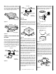
Step 4. Fireplace should be secured to side framing members using the full length nailing tabs at the top and bottom of the fireplace front face. Use 8d nails (Figure 17 ). Step 6. Connect the 6" (102 mm) Class 0 air duct provided by installer, to the duct collar on the fireplace and secure with two (2) screws from the kit’s hardware package. Step 7. Route the Class 0 air duct out the back or side wall, up through the ceiling or floor joists to an outside wall.
Note: If there is a room above ceiling level, firestop spacer must be installed on the bottom side of the ceiling. If an attic is above ceiling level, firestop spacer must be installed on top side of ceiling joist (Figures 21 and 22 ). Room Above Room Above F8FS30-2 Firestop Spacer 2" Min. Air Space 2" Min. Air Space If the flue has been installed correctly, it will not separate when you test it. Also, the inner flue joint where each section is joined should be tight and flat without gaps (Figure 26 ).
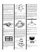
Security chimney sections do not need to be screwed together. Additional reinforcement is not necessary except in certain offset conditions (refer to page 14, Figure 39 ). FTF8 Chimney Do Not Seal Flashing Spacers Step 5. The height of vertical chimney pipe supported only by the fireplace must not exceed 30'. Chimney heights above 30' must be supported by a Model FTF8-S4 stabilizer installed at 30' intervals. Note: The Model FTF8-S4 adds 3" net effective height to the total chimney system.
Using a FTF8-CTDT Chase Termination: TEN FOOT RULE SUMMARY Refer to specific installation instructions included with the FTF8-CTDT chase termination for clearance and installation details. The minimum chimney height above the roof and/or to adjacent walls and buildings is specified by all major building codes. Using a FTF8-CT1 Chase Termination: If the horizontal distance from the peak of the roof is less then 10', the top of the chimney must be at least 2' above the peak of the roof.
4. Determine amount of chimney height required by subtracting total combined height of all pre-selected components (fireplace and chimney components from total desired height.) Reference Vertical Elevation Chart and determine the number of chimney sections (quantity and length) required. Step 2. Use “Height of Chimney Only” column in The Vertical Elevation Chart to determine combinations of chimney used above return elbow to achieve desired heights.
OFFSET ELEVATION CHART A1 Return Elbow 20' Max. B1 Stabilizer 10' Max.
Measure height to the ceiling from the top of fireplace-dimension “B.” Use the appropriate Offset Elevation Chart to find dimension “A.” Mark point where you will drive your nail to show the center point for your offset ceiling cut. Chimney Section No Joi Scre nts ws Fo Re r F qu irs ire t6 dI 'o n fO ffs et Scr Eve ews ry Re Joi qu nt ired Pa st At 6' Joints Step 2. Proceed by using the Straight Up Installation Instructions for cutting and framing ceiling and roof openings. 4' No.
Operate the actuator through several cycles including the "lock position. Ensuring proper operation and freedom of movement. Return the actuator arm to the locked position. The unit has been tested for use with any unvented log sets having a maximum rating of 26,000 BTU. The minimum mantle configuration for these log sets are outlined in Figures 46 and 47. Log sets with 40,000 BTU may be installed provided that no combustible mantle projections are placed lower than 18 inches from the fireplace opening.
Glass Doors FIREPLACE FINISHES If glass doors are to be installed on these fireplaces, refer to specific installation instructions packed with the glass doors. Use only the doors that are listed for use with these fireplaces. Use of other non-listed glass door on these fireplaces may constitute a potential fire hazard and is not recommended. Mantels and Trim CAUTION: CERTAIN GLASS DOORS OVERLAP THE BLACK METAL FACING OF THE FIREPLACE.
A wall shield is required where a continuous perpendicular side wall is within 12" of the fireplace opening, (Figure 49 ). Use a 24" W x 30" H wall shield constructed of millboard or a durable, noncombustible material having an equal or greater insulating value than K = .54BTU/ IN FT2 HR °F. At no time may a perpendicular side wall be closer than 8". If fireplace is installed diagonally across a 90° corner; no wall shields are required.
A ³⁄₄" marble slab set in ¹⁄₂" mortar covers the brick, “R” for the marble and mortar becomes: INSTALLATION COMPONENTS The following items are available for use in the installation of this appliance. “R”M = r x TM = 0.09 x ³⁄₄" = .068 “R”M = r x TM = 0.20 x ¹⁄₂" = .10 The sum of all “R values” is: 5 1/2" .70 + .10 +. 068 + .10 = .968 This would be an acceptable combination of material for the hearth extension since the total calculated “R value” of the materials used exceeds the required “R value” of 0.
INSTALLATION COMPONENTS (FBK-200 Models Only) Firestop Spacer (30°) 63L32 F8FS30-2 Forced Air Blower Kits -Single Speed -Variable Speed Offset/ Return Package (30°) 63L22 Storm Collar Locking Band Firestop Spacer (Flat) 63L25 63L59 63L60 63L31 FBK-100 FBK-200 Chase Termination (Square) 63L51 FTF8-CT2 Chase Termination (Round) 63L45 FTF8-CTDT FTF8-ES30 Flashing Stabilizer 80L84 80L85 63L38 63L39 F8F6 F8F12 FTF8-S4 Chase Termination 96L20 FTF8-CTT Round Termination 63L42 FTF8-CT
The manufacturer reserves the right to make changes at any time, without notice, in design, materials, specifications, prices and also to discontinue colors, styles and products. Consult your local distributor for fireplace code information. Printed in U.S.A. © 2000 by LENNOX 20 P/N 700,009M REV. D 11/2003 NOTE: DIAGRAMS & ILLUSTRATIONS NOT TO SCALE.