OPERATING INSTRUCTIONS PA AMPLIFIERS A-2030 L A-2060 L A-2120 L A-2240 L A-2030 H A-2060 H A-2120 H A-2240 H A-2030 SA A-2060 SA A-2120 SA A-2240 SA Please follow the instructions in this manual to obtain the optimum results from this unit. We also recommend that you keep this manual handy for future reference.
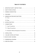
TABLE OF CONTENTS 1. IMPORTANT SAFETY INSTRUCTIONS……………………….……….. 3 2. SAFETY PRECAUTIONS ………………………………………………… 3 3. GENERAL DESCRIPTION ……………………………………….………. 5 4. FEATURES…………………………………………………………………. 5 5. NOMENCLANTURE AND FUNCTIONS 5.1 Front …………………………………….………………..……………. 6 5.2 Rear ……………………………………………….………..………….. 6 6. MUTING FUNCTION ………………………………………..…………….. 7 7. CONNECTIONS 7.1. Input Connections ……………….………………………….….……. 8 7.2. Output Connections ………………………………….………..…….. 9 7.3.
1. IMPORTANT SAFETY INSTRUCTIONS 2. SAFETY PRECAUTIONS • Before installation or use, be sure to carefully read all the instructions in this section for correct and safe operation. • Read these instructions. • Keep these instructions. • Be sure to follow all the precautionary instructions in this section, which contain important warnings and/or cautions regarding safety. • Heed all warnings. • Follow all instructions. • After reading, keep this manual handy for future reference.
When the Unit is in Use • Install the equipment rack on a stable, hard floor. Fix it with anchor bolts or take other arrangements to prevent it from falling down. • Should the following irregularity be found during use, immediately switch off the power, disconnect the power supply plug from the AC outlet and contact your nearest TOA dealer. Make no further attempt to operate the unit in this condition as this may cause fire or electric shock.
3. GENERAL DESCRIPTION TOA’s Basic Amplifiers A-2030, A-2060, A-2120 and A-2240 are high cost-performance mixer power amplifiers suited for broadcasting paging or background music in schools, offices, shops, factories, mosques, churches and large rooms. 4. FEATURES • High durability, high reliability, and high cost performance. • Three microphone inputs, two AUX inputs, and one recording output. • Speaker output of constant voltage distribution system (70V or 100V) and low impedance (4Ω).
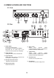
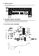
5. NOMENCLATURES AND FUNCTIONS 5.1. Front 5.2. Rear 1. Power Switch Press to turn ON the power. Press again to turn the power STANDBY. Disconnect the AC mains plug or DC Terminal to shut the power OFF completely. 6. Bass Control Adjusts bass response. Rotate counterclockwise to reduce it. The maximum position provides flat characteristics. 2. Power Indicator Lights green when power is switched ON. 7. Treble Control Adjusts treble response. Rotate counterclockwise to reduce it.
10. Output Terminals Connect to speakers. When connecting speakers use only one of the speaker output terminals, low or high impedance. 13. AUX Input Terminals -20dB, 10kΩ, unbalanced. Monaural RCA pin jacks. Accept external equipment output signal. 11. Terminal Cover To avoid electric shock by high voltage from output terminal, put back the terminal cover after connecting speaker cords. 14.
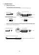
7. CONNECTIONS 7.1. Input Connections ● Mic1, Mic2, Mic3 Connection (Phone Plug) Because MIC input is electronically balanced type, it uses double pole phone plug. MIC Double Pole Plug Two Core Shielded Cable MIC To Mic ic Phantom Switch Position In the case of Dynamic Microphone In the case of Phantom Power Microphone PHANTOM OFF PHANTOM OFF ON ON However, the microphone input circuit is in a condition of unbalance when it uses Single pole type.
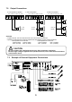
7.2. Output Connections ● Low Impedance Speaker - +24V COM 4Ω COM 70V 100V 4 - 16Ω Speaker ● 70V Line Speaker - +24V COM 4Ω COM 70V 100V ● 100V Line Speaker - +24V COM 4Ω COM 70V 100V 70V Line Speaker 100V Line Speaker CAUTION! • Tripartite the 4Ω, 70V and 100V terminals cannot be used at the same time. • Impedances indicated at the terminal represent the total speaker system (load) impedances.
8. INSTALLATION Keep the unit’s all sides over 10 cm (3.94 inches) away from object that may obstruct air flow to prevent the unit’s internal temperature rise. 9. VOLUME CONTROL SETTINGS Output levels are adjustable with individual volume controls. For music play or announcement, adjust the corresponding volume control so that the red peak indicator lights intermittently. Note that the sound quality is downgraded when the peak indicator remains lit. 10.
. DIMENSIONAL DIAGRAM ● A-2030 L, A-2030 H, A-2030 SA ● A-2060 L, A-2060 H, A-2060 SA units: mm(inches) ● A-2120 L, A-2120 H, A-2120 SA ● A-2240 L, A-2240 H, A-2240 SA 11
. SPECIFICATIONS A-2030 L-H-SA Model No.