OPERATING INSTRUCTIONS PA AMPLIFIER P-1812 Please follow the instructions in this manual to obtain the optimum results from this unit. We also recommend that you keep this manual handy for future reference.
TABLE OF CONTENTS 1. SAFETY PRECAUTIONS ............................................................................... 3 2. GENERAL DESCRIPTION ............................................................................. 4 3. FEATURES .......................................................................................................... 4 4. NOMENCLATURE AND FUNCTIONS Front .........................................................................................................................
1. SAFETY PRECAUTIONS • Be sure to read the instructions in this section carefully before use. • Make sure to observe the instructions in this manual as the conventions of safety symbols and messages regarded as very important precautions are included. • We also recommend you keep this instruction manual handy for future reference.
CAUTION When Installing the Unit • Never plug in nor remove the power supply plug with wet hands, as doing so may cause electric shock. • When unplugging the power supply cord, be sure to grasp the power supply plug; never pull on the cord itself. Operating the unit with a damaged power supply cord may cause a fire or electric shock. • When moving the unit, be sure to remove its power supply cord from the wall outlet.
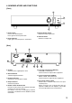
4. NOMENCLATURE AND FUNCTIONS [Front] 4 2 1 3 1. Power switch Press to turn ON the power. Press again to turn the power OFF. 3. Master volume control Adjusts the output signal level. 4. LED level meter Indicates an output level. 2. Power indicator Lights green when the power is switched on. [Rear] 5 9 6 7 8 10 5. AC inlet Connects to the supplied power cord. 6. Ground terminal A functional ground terminal. 7. DC input terminals Connect to a 24 V DC power supply. 8.
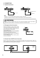
5. CONNECTIONS 5.1. Speaker Connections INPUT 24 V C C INPUT 83 Ω 4 16Ω 100 V 24 V C C 83 Ω 4 16Ω 100 V Total impedance: 83 Ω 4 – 16 Ω 100 V line Notes • Both the 4 – 16 Ω and 100 V terminals cannot be used at the same time. • Impedances indicated in the figures represent the total speaker system (load) impedances. WARNING Be sure to attach the supplied terminal cover after connection completion.
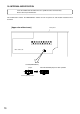
5.4. Emergency Input and Control Input Terminal Connections While the Emergency control input terminals remain shorted, the power of all the connected A-1800 series and P-1812s is turned on, and the A-1800's ZONE 1 and 2 speaker outputs are enabled, allowing only Emergency input signals to go through bypassing the master volume control. Opening the control input terminals automatically returns the muted signals to the original level.
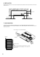
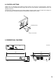
6. INSTALLATION Keep the unit's all sides over 10 cm away from objects that may obstruct air flow to prevent the unit's internal temperature rise. Over 10 cm Over 10 cm Over 10 cm 7. RACK MOUNTING To mount the unit in a standard 19" equipment rack, use the optional MB-25B Rack Mounting Bracket. Attach the MB-25B to the unit using the supplied 4 screws. When using other screws, each screw must be shorter than 16 mm.
8. CONTROL SETTING Output levels are adjustable with the Master Volume Control. For music play or announcements, adjust the Control so that the red indicator doesn't light. Note that the sound quality is downgraded when the red indicator remains lit. To prevent the accidental change of the setting of Master Volume Control, remove its knob after setting it to the desired position and attach the optional YA-920 Volume Control Cover instead. YA-920 (optional) Volume control knob 9.
. INTERNAL MODIFICATION Leave the modification described here to a qualified service technician only. Please consult your TOA dealer. This modification enables the EMERGENCY Control to turn the power off and disable broadcast when activated. [Upper view without case] Rear panel Main circuit board SJP100 (EMERGENCY) Jumper ON OFF Factory-preset position 10 Install the SJP100 jumper to "OFF" position.
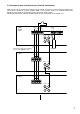
REMOTE IN + – EMERGENCY CONTROL INPUT LEVEL (0 dB/–10 dB) LINE IN 10 kΩ 0 dB/–10 dB Relay POWER Power for audio section Power for control section MASTER volume Emergency mode ON/OFF Power ON/OFF OT Fuse Output level meter PA 0 dB JP Fuse (70 V) PT (Relay) LINE OUT 0 dB/600 Ω 240 V 230 V – Fuse INPUT POWER switch 220 – 230 V AC or 240 V AC, 50/60 Hz + 24 V C C 4 – 16 Ω 83 Ω (100 V) 11.
. SPECIFICATIONS Power Source Rated Output Power/Current Consumption Frequency Response Distortion Input Output S/N Ratio (Band Pass: 20 – 20,000 Hz) Control Input Indicator Operating Temperature Finish Dimensions Weight 220 – 230 V AC or 240 V AC, 50/60 Hz 24 V DC (M4 screw terminal*2) 120 W AC operation: 258 W (rated output), 94 W (EN60065) Under 320 mA (when power switch is OFF) 24 V DC operation: 7.0 A (rated output), 2.