
User Manual


SPEAKER SELECTOR
OPERATING INSTRUCTIONS
SS-9001
Thank you for purchasing TOA's Speaker Selector.
Please carefully follow the instructions in this manual to ensure long, trouble-free use of your equipment.
1. SAFETY PRECAUTIONS
• Before installation or use, be sure to carefully read all the instructions in this section for correct
and safe operation.
• Be sure to follow all the precautionary instructions in this section, which contain important
warnings and/or cautions regarding safety.
• After reading, keep this manual handy for future reference.
Indicates a potentially hazardous situation which, if mishandled,
could result in death or serious personal injury.
WARNING
• External wiring connected to the terminals marked with requires installation by an instructed
person.
2. GENERAL DESCRIPTION
The SS-9001 is a speaker selector used with 9000 series amplifier.
It selectively distributes each of 2 inputs to the same 4 output zones.
3. SPECIFICATIONS
Supplied from the optional AD-246 AC adapter or
an external 24 V DC/200 mA power supply.
120 mA
No-voltage make contact input (polarized), open voltage: 24 V DC,
short-circuit current: 3 mA
Under 240 W (70 V/100 V line)
Removable terminal block (2 pins)
Removable terminal block (10 pins)
–10 to +40°C
Case: Surface-treated steel plate
112 (w) x 197 (h) x 30 (d) mm
530 g
Removable terminal plug (2 pins) x 6, Removable terminal plug (10 pins) x 1,
Cord clamp x 1, Tapping screw (4 x 20) x 4
Power Source
Current Consumption
Control Signal
Control Power
Speaker Terminal
Control Terminal
Operating Temperature
Finish
Dimensions
Weight
Accessories
Note: The design and specifications are subject to change without notice for improvement.
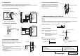
4. NOMENCLATURE AND FUNCTIONS
9000 SERIES
SPEAKER SELECTOR
ZONE 1IN 1
70V/100V MAX. 240W
70V/100V MAX. 240W
IN
2
ZONE 2
ZONE 2
ZONE 1
G
G
G
G
ZONE 4
ZONE 3
ZONE 3
CTRL IN
DC IN
24V
120mA
IN
2
IN
2
ZONE 4
IN
2
IN
2
1
2
3
4
5
1
30
18 1870
112
157
197
17710
[Left side] [Front] [Right side]
1. Speaker input terminals [IN 1, IN 2]
2-pin removable terminal blocks.
Connect the speaker output (high impedance
line, up to 240 W) from the power amplifier to
each terminal.
Short the IN 2 terminal's pins when only the
IN 1 terminal is used.
2. Control input terminal [CTRL IN]
8 pins in the 10-pin removable terminal block.
Receives the control signals (polarized non-
voltage contacts) from the ZP-001T when the
9000 series amplifier is in the Matrix "Sub-
Mode" (single output or BGM/PAGE), and
activates the inner relays.
This terminal can also receive control signals
from the control output terminals of the 9000
series amplifier or C-001T Control I/O
Expansion Module. (For details, refer to the
9000 series amplifier's instruction manual.)
3. DC power input terminals [DC IN]
Requires the power input of 24 V DC.
DC input terminal or 2 pins in the 10-pin
removable terminal block.
Connect the power source that can supply
200 mA or more to this terminal.
The optional AD-246 AC Adapter can be
used for the power supply.
4. Cord clamp
Fixes the AC adapter's power cord.
5. Speaker output terminals [ZONE 1/2/3/4]
2-pin removable terminal blocks.
Connect speakers to each terminal, which is
capable of delivering 240 W output on a line.
Unit: mm