
Instruction Manual


5
4. INSTALLATION
• Use a power source of 220 VAC, 50/60 Hz.
• Connect the signal grounding terminal to the ground.
• Avoid installing the unit in humid, dusty or vibratory locations as well as locations where the unit is exposed
to steam or oil-contaminated smoke.
• Do not block vents provided in both the top and bottom surfaces.
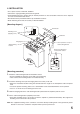
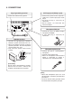
• When mounting on the wall, fix securely as illustrated below.
[Mounting diagram]
[Mounting procedure]
1. Attach the wall mounting bracket to the bottom surface.
• Use the supplied two machine screws (M4 x 8) for mounting.
• Take care that the mounting bracket is installed correctly.
2. Install the mounting screw (for the hanging hole in the center) in the wall.
• Select the installation location taking into consideration the length of the microphone cable and power
cord.
• To secure speaker mounting, make sure a solid wooden stud is located behind the screw's position.
• Leave 2 – 3 mm of the screw sticking out of the wall.
3. Hook the hanging hole in the wall mounting bracket (attached to the amplifier) onto the screw.
4. Fix the wall mounting bracket (amplifier) to the wall.
• Using two mounting screws, fix securely so that the amplifier is positioned horizontally. Also, tighten the
mounting screw referred to in Step 2 above.
Note: The supplied mounting screws cannot be used when directly installing them in the plywood or plaster
boards. In such cases, contact the shop from whom you have purchased.
IN
F
O
R
M
A
T
IO
N
A
M
P
LIF
IE
R
T
A
-1
02
2 – 3 mm
Mounting screw
(tapping screw)
Wall mounting
bracket
Amplifier
Screw (machine screw) for
wall mounting bracket
Bracket mounting hole
in the bottom surface
Wall stud
Wall board
Hanging hole
45 mm
45 mm
2
1
4
3