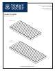
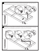
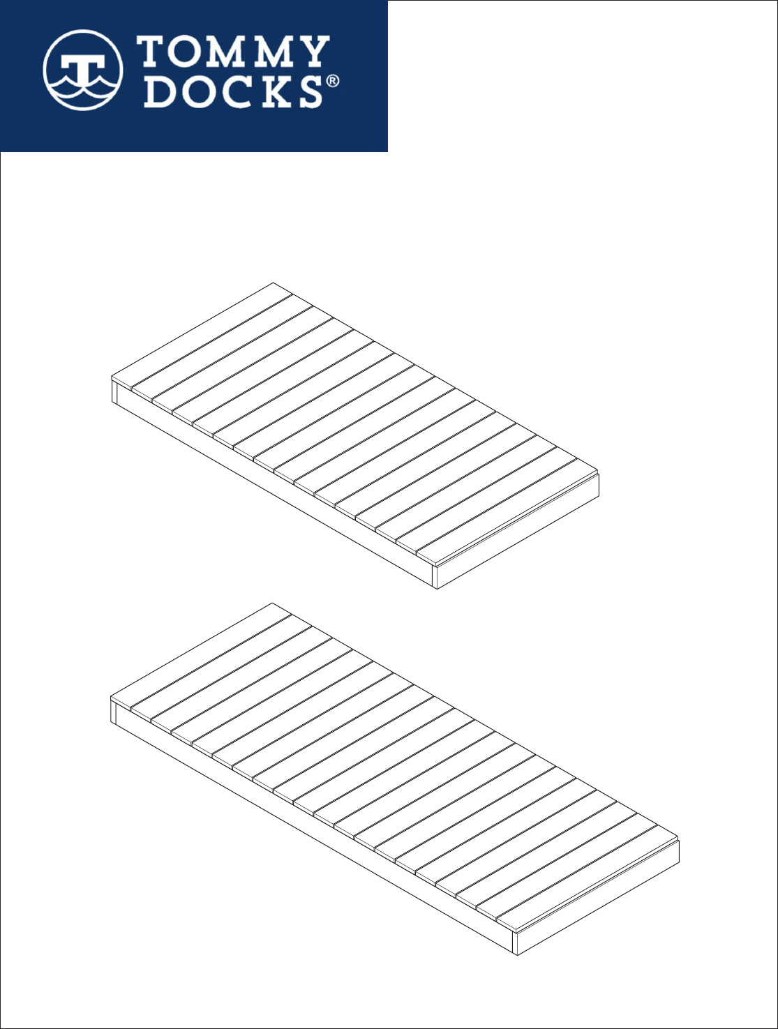
Tommy Docks 4003 Dixie Ave, Wausau, WI 54401 Phone : 715-842-3804 Toll Free : 866-675-1880 Fax : 715-842-3420 Cedar Dock Kit Assembly Instructions 4’ x 8’ Cedar Dock Kit 4’ x 10’ Cedar Dock Kit www.tommydocks.
4’ x 8’ Cedar Dock Kit Components 5/4 x 6” x 47 3/4” Deck Board Qty 16 2” x 6” x 21 5/8” Support Qty 2 2” x 6” x 47 3/4” End Rail Qty 2 2” x 6” x 93” Side Rail Qty 2 2” x 6” x 93” Center Rail Qty 1 4’ x 10’ Cedar Dock Kit Components 5/4 x 6” x 47 3/4” Deck Board Qty 20 2” x 6” x 21 5/8” Support Qty 2 2” x 6” x 47 3/4” End Rail Qty 2 2” x 6” x 117 1/8” Side Rail Qty 3 2” x 6” x 117 1/8” Center Rail Qty 1
4’ x 8’ Cedar Dock Kit Hardware Note: Dock may be assembled using either galvanized nails (included) or galvanized deck screws (recommended). These instructions depict assembly using galvanized deck screws.
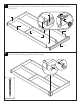
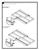
1 Lay out two boards as shown. Align one end of the End Rail with end of Side Rail (1a). Align End Rail to Side Rail using a Quick Square and pre-drill one hole into the End Rail using a Drill Bit (1b). Quick Square End Rail End Rail Drill Bit Side Rail 1a Side Rail 1b Side Rail Support Support Center Rail End Rail 2 Secure End Rail to Side Rail using one (1) Deck Screw (2a). Use the Driver Bit to fully tighten the Deck Screw (2b).
3 Using the Drill Bit, drill two (2) more holes (3a & 3b) through the End Rail and into the Side Rail. Secure End Rail to Side Rail using two (2) Deck Screws (3c). Use the Driver Bit to fully tighten the Deck Screws (3d). Repeat this procedure for three (3) ramaining corners. 3a 3b 3d 3c 2x 4 Measure approximately 24” to center the Center Rail (4a). Using a Pencil and a Sliding Square, extend a vertical line onto the side of the End Rail (4b). Repeat this procedure for other end of the Center Rail.
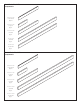
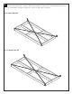
5 Position the two (2) Supports as shown. The supports used for the 4’ x 8’ Cedar Dock Kit are located 57” from each end rail as shown (5a). The supports used for the 4’ x 10’ Cedar Dock Kit are located 64” from each end rail as shown (5b).
6 Using a Tape Measure, measure diagonally from corner to corner to make sure the frame is square. You will know the frame is square if both measurements are the same. If the measurements are not the same, adjust the frame slighlty left or right until the frame is squared.
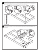
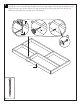
7 Using a Pencil and a Sliding Square, extend a vertical line onto the side of the Side Rail (7a). Using a Drill Bit, drill one (1) hole through the Side Rail and into the Support (7b). Secure the Support to the Side Rail using one (1) Deck Screw (7c). Use the Driver Bit to fully tighten the Deck Screw (7d). Repeat this procedure for the other end of the Support.
8 Using a Drill Bit drill two (2) holes through the Side Rail and into the Support (8a & 8b). Secure the Support to the Side Rail using two (2) Deck Screws (8c). Use the Driver Bit to fully tighten the Deck Screws (8d). Repeat this procedure for the other end of the Support.
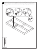
9 Using a Drill Bit, drill one (1) hole through the End Rail and into the Center Rail (9a). Secure the End Rail to the Center Rail using one (1) Deck Screw (9b). Use the Driver Bit to fully tighten the Deck Screw (9c). Repeat this procedure for the other end of the Center Rail. 9a 9b Center Rail 9c End Rail Center Rail End Rail 1x 10 Using a Drill Bit, drill two (2) holes through the End Rail and into the Center Rail (10a & 10b).
In order to determine spacing for the Deck Boards, use a Pencil and a Measuring Tape and measure along each Side Rail every 6” from the End Rail. The final mark should be at the very end of the other End Rail. NOTE: If you are assembling a 4’ x 8’ Cedar Deck Kit, sixteen (16) boards will be installed. If you are assembling a 4’ x 10’ Cedar Deck Kit, twenty (20) Deck Boards will be installed.
13 As you begin to install the reamining Deck Boards, the leading edge of each Deck Board must line up with the 6” pencil marks on each Side Rail (13a & 13b). Leading edge of deck board 13a 13b Pencil Mark 14 Install final Deck board making sure the Deck Board sits flush with the other End Rail.
15 Using a Drill Bit, pre-drill three (3) holes through the Deck Board and into the frame in the three (3) areas indicated below (a total on nine (9) hole swill be drilled) (15a). Secure the Deck Board to the frame using three (3) 2- 1/2” Deck Scr ews per rail (15b). Use the Driver Bit to fully tighten all nine (9) Deck Screws (15c). Repeat this procedure for the remaining Deck Boards.